107
PDP-433CMX
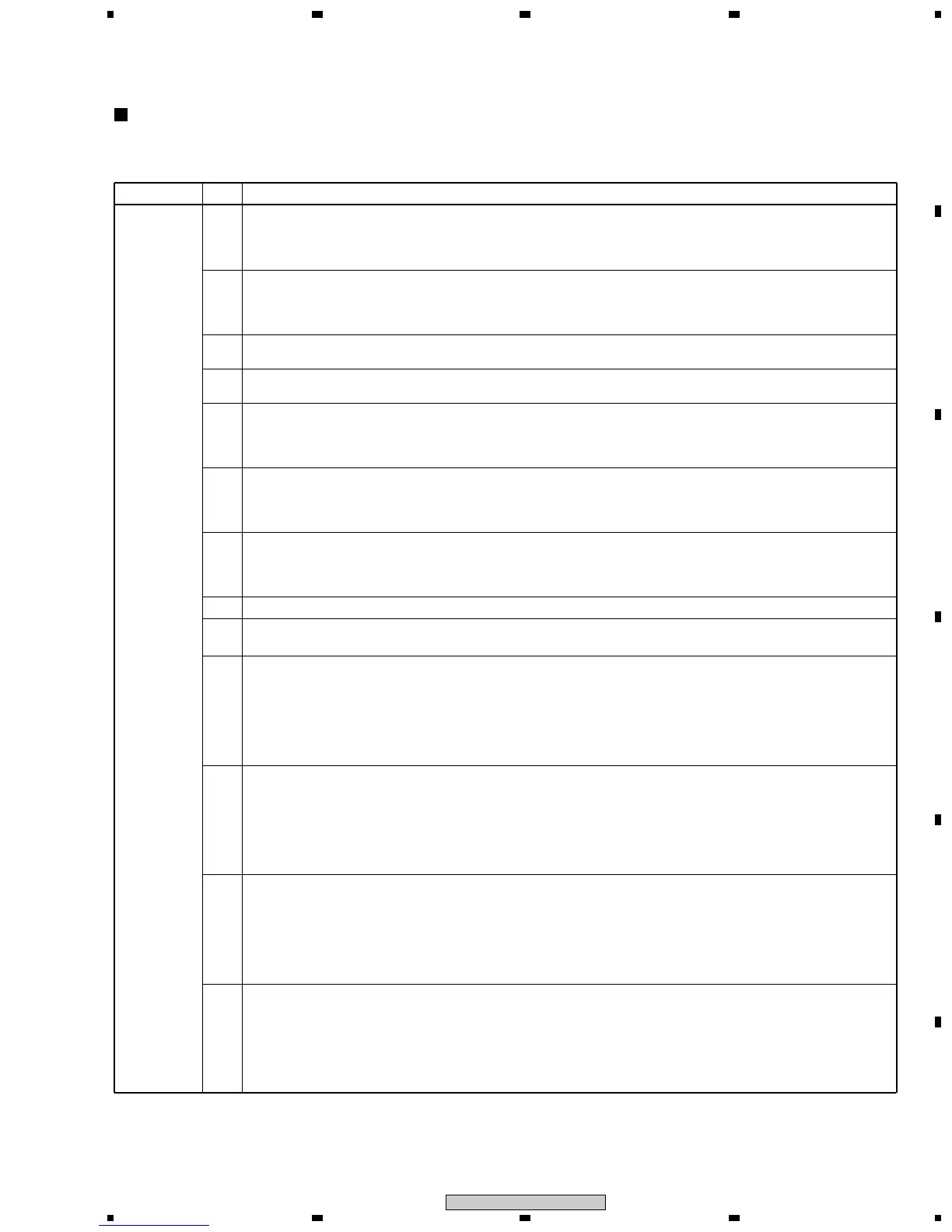
5
678
5
6
7
8
C
D
F
A
B
E
Input Signal
Step Adjusting Method
Video signal
1
Connect a Video Card to the RGB Assy through a jig cable to measure the RGB Assy.
(See "Diagnosis of the Video Card (PDA-5002)" of 7.1.4 DISASSEMBLY.)
The signal level cannot be measured without a jig cable.
Note: Be careful of the jig cable connector when connecting.
2
Input a 525i component signal to INPUT 1 and INPUT 2.
Use a signal consisting of the luminance signal only, such as a ramp signal or STEP signal, whose black level (0IRE)
and gradation can be checked.
Note: You can use a Y (luminance) signal of the standard NTSC component video signal.
3
In the signal input function (INPUT1 or INPUT2), set the display mode of the VIDEO signal to COMPONENT.
MENU → SETUP → VIDEO SIGNAL : COMPONENT
4
Set the unit to Standby mode then to Factory mode.
MENU → SET → POWER ON
5
Turn the ACL SW setting to OFF.
INITIALIZE mode
ACL SW : "3" key
Select OFF with the right and left keys.
6
Decrease the MAT CONT adjustment value of OFFSET-RGB1 by 3.
OFFSET mode: Select RGB 1 mode with the top and bottom keys.
MAT CONT : "1" key
Decrease the adjustment value by 3 with the right and left keys.
7
Decrease the MAT BRIGHT adjustment value of OFFSET-RGB1 by 2.
OFFSET mode: Select RGB 1 mode with the top and bottom keys.
MAT BRIGHT : "2" key
Decrease the adjustment value by 2 with the right and left keys.
8 Take a trigger of the oscilloscope with HD_PLL (3.3Vp-p) of K4805.
9
Measure the signal waveform of the Green signal at K4603, and measure the black level (0IRE) and amplitude.
10
AD R LOW adjustment
Measure the black level (0IRE) of the Red signal at K4602, and adjust the level of AD R LOW so that its black level
(0IRE) becomes the same as that of the Green signal measured in step 9.
Tolerance: ± 0.05V
OFFSET mode: Select RGB 1 mode with the top and bottom keys.
AD R LOW : "9" key
Adjust with the right and left keys.
11
AD R HIGH adjustment
Measure the signal amplitude of the Red signal at K4602, and adjust the level of AD R HIGH so that its signal
amplitude becomes the same as that of the Green signal measured in step 9.
Tolerance: ± 0.05V
OFFSET mode: Select RGB 1 mode with the top and bottom keys.
AD R HIGH : "6" key
Adjust with the right and left keys.
12
AD B LOW adjustment
Measure the black level (0IRE) of the Blue signal at K4604, and adjust the level of AD B LOW so that its black level
(0IRE) becomes the same as that of the Green signal measured in step 9.
Tolerance: ± 0.05V
OFFSET mode: Select RGB 1 mode with the top and bottom keys.
AD B LOW : "11" key
Adjust with the right and left keys.
• A Video Card (PDA-5002 or equivalent) is necessary for white balance adjustment for video signal of the RGB Assy.
• Adjust with video system signal (525i) and RGB (PC VGA) signal.
• Adjust so that the level and amplitude of the RED and BLUE signals become the same, referring to the GREEN signal.
White-Balance Adjustment
13
AD B HIGH adjustment
Measure the signal amplitude of the Blue signal at K4604, and adjust the level of AD B HIGH so that its signal
amplitude becomes the same as that of the Green signal measured in step 9.
Tolerance: ± 0.05V
OFFSET mode: Select RGB 1 mode with the top and bottom keys.
AD B HIGH : "8" key
Adjust with the right and left keys.
 Loading...