133
PDP-433CMX
5
678
5
6
7
8
C
D
F
A
B
E
Number
of
Blinks
P.D. Point in
Operation
Error Point Possible Part in failure Circuit State
P.D. Circuit
in Operation
Diagnosis Condition
1 Y DRIVE
IC2206, IC2214 (Pulse module), IC2203, IC2204,
IC2212, IC2213, IC2216, IC2217, R2209
K2211 Lo VCP OCP
2 Y DC DC
VOFS D/D CONV. BLOCK (Y DRIVE Assy) IC2702, IC2709, IC2715 K2712 Lo VOFS OVP
VOFS D/D CONV. BLOCK (Y DRIVE Assy)
IC2701, IC2702, IC2709, IC2715
K2709 Lo VOFS UVP
Drive section (control signals, output elements etc.)
in normal operation
Q2211, Q2212, R2277, IC2208, IC2210 VOFS D/D CONV. BLOCK in normal operation
VH D/D CONV. BLOCK (Y DRIVE Assy) IC2712, IC2716 K2719 Lo VH OVP
VH D/D CONV. BLOCK (Y DRIVE Assy) IC2711, IC2712, IC2716
K2718 Lo VH UVP
Drive section (control signals, output elements etc.)
in normal operation
SCAN (A), (B) Assy SCAN IC VH D/D CONV. BLOCK in normal operation
IC5V D/D CONV. BLOCK (Y DRIVE Assy) IC2704, IC2706, IC2717 SCAN Assy in normal operation
SCAN (A), (B) Assy
Y DRIVE Assy
SCAN IC
K2713 Lo IC5V UVP
IC5V D/D CONV. BLOCK in normal operation
IC5V D/D CONV. BLOCK (Y DRIVE Assy) IC2704, IC2706, IC2717 SCAN Assy in normal operation
3 X DC DC
VRN D/D CONV. BLOCK (X DRIVE Assy) IC3702, IC3712 K3708 Lo VRN OVP
VRN D/D CONV. BLOCK (X DRIVE Assy) IC3701, IC3702, IC3712
K3705 Lo VRN UVP
Drive section (control signals, output elements etc.)
in normal operation
X DRIVE Assy Q3122 VRN D/D CONV. BLOCK in normal operation
4 X DRIVE X DRIVE Assy
IC3200, IC3201 (pulse module), IC3103, IC3104,
IC3106, IC3107, IC3110, IC3113, R3109
K3103 Lo VCP OCP
5
PS
X DRIVE Assy IC3200, IC3201 (Pulse module)
In a case where PD does not occur if the P4 connector is
disconnected
Y DRIVE Assy IC2206, IC2214 (Pulse module)
In a case where PD does not occur if the P3 connector is
disconnected
MX AUDIO Assy IC8601 (Audio IC)
In a case where PD does not occur if the P6 connector is
disconnected
In a case where PD does not occur if Pin 5 of the P2
connector is disconnected
SW POWER SUPPLY Module SW POWER SUPPLY Module
In a case where the voltage is not output even if the P4, P3,
P6 connectors and Pin 5 of the P2 connectors are
disconnected
6 ADR ADDRESS CONNECT A~D Assy
ADDRESS CONNECT A - D Assy,
RESONANCE Assy,
D/D CONV. BLOCK (DIGITAL VIDEO Assy)
Disconnection of the D8 - D15 connectors
7 ADR K RESONANCE Assy
TCP damage of IC6704 (ICP), disconnection of the
D16 and D17 connectors, panel microcomputer is
defective, external Flash ROM of the panel
microcomputer is defective.
8 DIGITAL
DC DC
D/D CONV. BLOCK (DIGITAL VIDEO Assy) IC1901
K1901 Lo
5.0V OVP
ADR. PD
ADR. K. PD
K1902 Lo 5.0V UVP
D/D CONV. BLOCK (DIGITAL VIDEO Assy) IC1901
K1903 Lo 3.3V OVP
K1904 Lo 3.3V UVP
D/D CONV. BLOCK (DIGITAL VIDEO Assy) IC1901
K1905 Lo 2.5V OVP
K1906 Lo 2.5V UVP
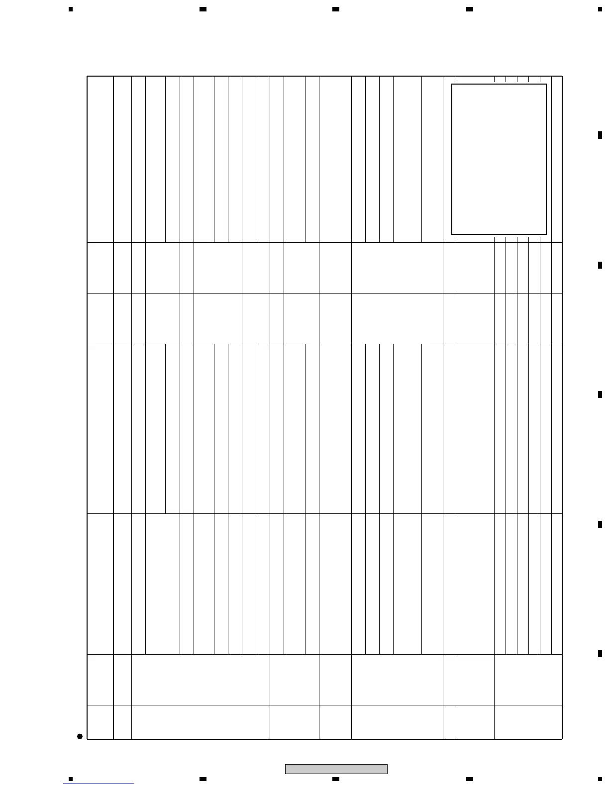
Diagnosis of error points in the various protection-circuit (P.D. circuits) operations (Red "STANDBY/ON" LED blinks)
Note on PS PD
The condition that Red "STANDBY/ON" LED
blinks five times (power supply PD)
1 When the internal protection circuit of the
SW POWER SUPPLY Module worked
2 When a microcomputer was not able to
identify the PD point
↓
Care must be taken because five blinks of
the red LED does not always mean that the
protection circuit of the SW POWER SUPPLY
Module is activated.
 Loading...