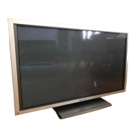
PDP-5010FD
115
5678
56
7
8
C
D
F
A
B
E
×4
Access to PCB Assys
2
1
Remove the four screws.
2
Remove the two screws.
3
Remove the four screws.
4
Remove the side input panel (8U).
SIDE IO Assy
1
Remove the two screws.
2
Remove the side input shield with PCB.
50F X DRIVE Assy
1
Remove the two screws.
2
Remove the function button shield with PCB.
50F Y DRIVE Assy
2
1
1
3
2
1
1
1 1
4
2
Side input panel (8U)
Side input shield
Function button shield
SIDE KEY Assy
50F Y DRIVE Assy
Sub frame L Assy 507
Capacitor
50F X DRIVE Assy
FHD POWER
SW Assy
SIDE IO Assy
1
1
2
POWER SUPPLY
Unit
PCB base
NG
OK
FHD FAN CONNECT
Assy
• For 50F X DRIVE Assy
• For 50F Y DRIVE Assy
• For SIDE IO Assy
3
Diagnose the 50F Y DRIVE Assy.
3
Diagnose the 50F X DRIVE Assy.
Caution:
As the two capacitors on the 50F Y DRIVE Assy are located very close to
sub frame L Assy 507, if the former Assy is tilted toward the latter Assy
when disassembling, they may come into contact with the latter Assy.
Therefore, before removing the 50F Y DRIVE Assy, be sure to tilt the
capacitors, as shown in the photo (away from sub frame L Assy 507).
Note:
When removing the POWER
SUPPLY Unit, be sure to remove
not only the POWER SUPPLY
Unit but entire PCB base.
50F Y DRIVE Assy
50F Y DRIVE
Assy
POWER SUPPLY
Unit
Styling of jumper wires around the FAN motor
 Loading...


