PDP-5010FD
8
1234
1 234
C
D
F
A
B
E
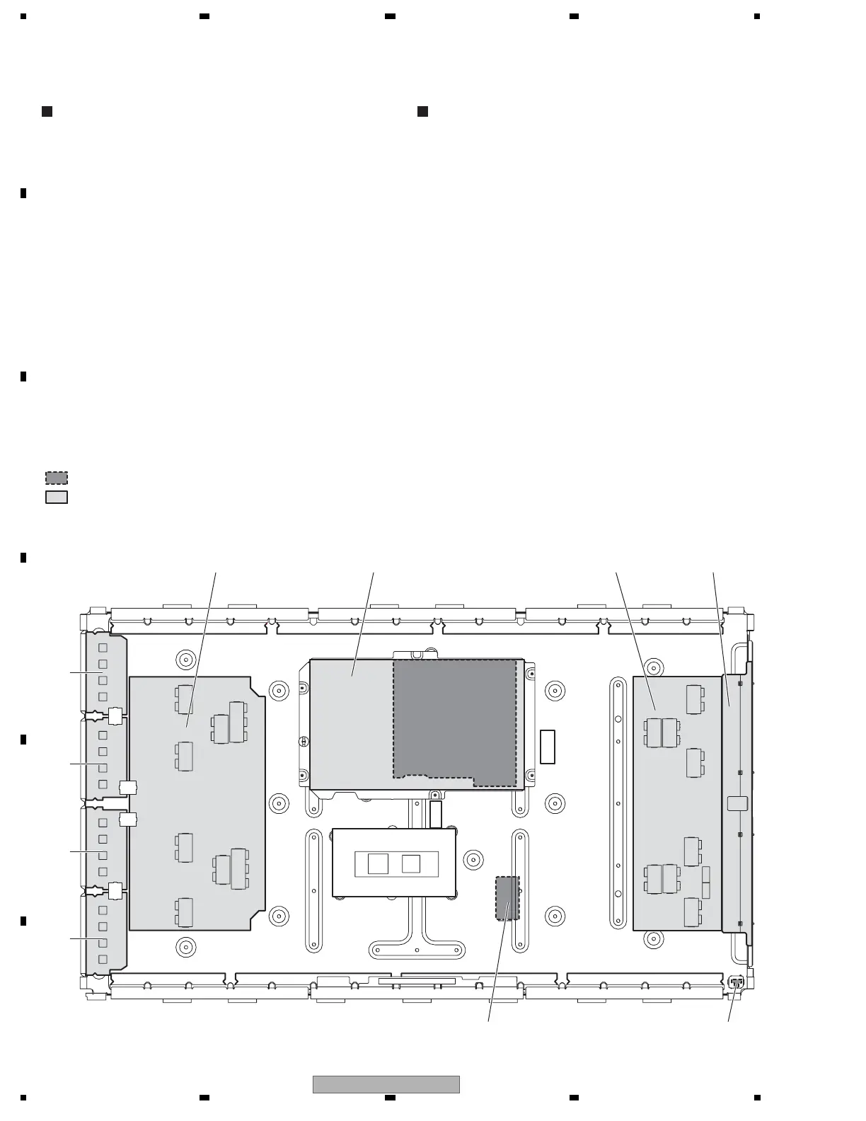
1.2 CHARGED SECTION AND HIGH VOLTAGE GENERATING POINT
Fig. High Voltage Generating Point (Rear view)
The places where voltage is 100 V or more except for the charged
places described above. If the places are touched, there is a risk of
electric shock.
The VSUS voltage remains for several minutes after the power to
the unit is turned off. These places must not be touched until
about 10 minutes after the power is turned off, or it is confirmed
with a tester that there is no residual VSUS voltage.
If the procedures described in “5.6.1 PANEL DRIVE-POWER
ON/OFF FUNCTION” are performed before the power is turned
off, the voltage will be discharged in about 30 seconds.
POWER SUPPLY UNIT ................................................... (205 V)
50F X DRIVE Assy .......................................................... (205 V)
50F Y DRIVE Assy ......................................... (−270 V to 400 V)
50F SCAN A Assy .......................................... (−270 V to 400 V)
50F SCAN B Assy ........................................... (−270 V to 400 V)
50F SCAN C Assy ........................................... (−270 V to 400 V)
50F SCAN D Assy ........................................... (−270 V to 400 V)
: Part is the High Voltage Generating Points
other than the Charged Section.
High Voltage Generating Point
50F Y DRIVE Assy POWER SUPPLY Unit 50F X DRIVE Assy Conductive plate X
50F SCAN D
Assy
50F SCAN C
Assy
50F SCAN B
Assy
50F SCAN A
Assy
Charged Section
The places where the commercial AC power is used without
passing through the power supply transformer.
If the places are touched, there is a risk of electric shock. In
addition, the measuring equipment can be damaged if it is
connected to the GND of the charged section and the GND of the
non-charged section while connecting the set directly to the
commercial AC power supply. Therefore, be sure to connect the
set via an insulated transformer and supply the current.
1. Power Cord
2. AC Inlet
3. Power Switch
4. Fuse (In the POWER SUPPLY Unit)
5. STB Transformer and Converter Transformer
(In the POWER SUPPLY Unit)
6. Other primary side of the POWER SUPPLY Unit
AC inlet Power switch
: Part is Charged Section.

 Loading...