PDP-5010FD
143
5678
56
7
8
C
D
F
A
B
E
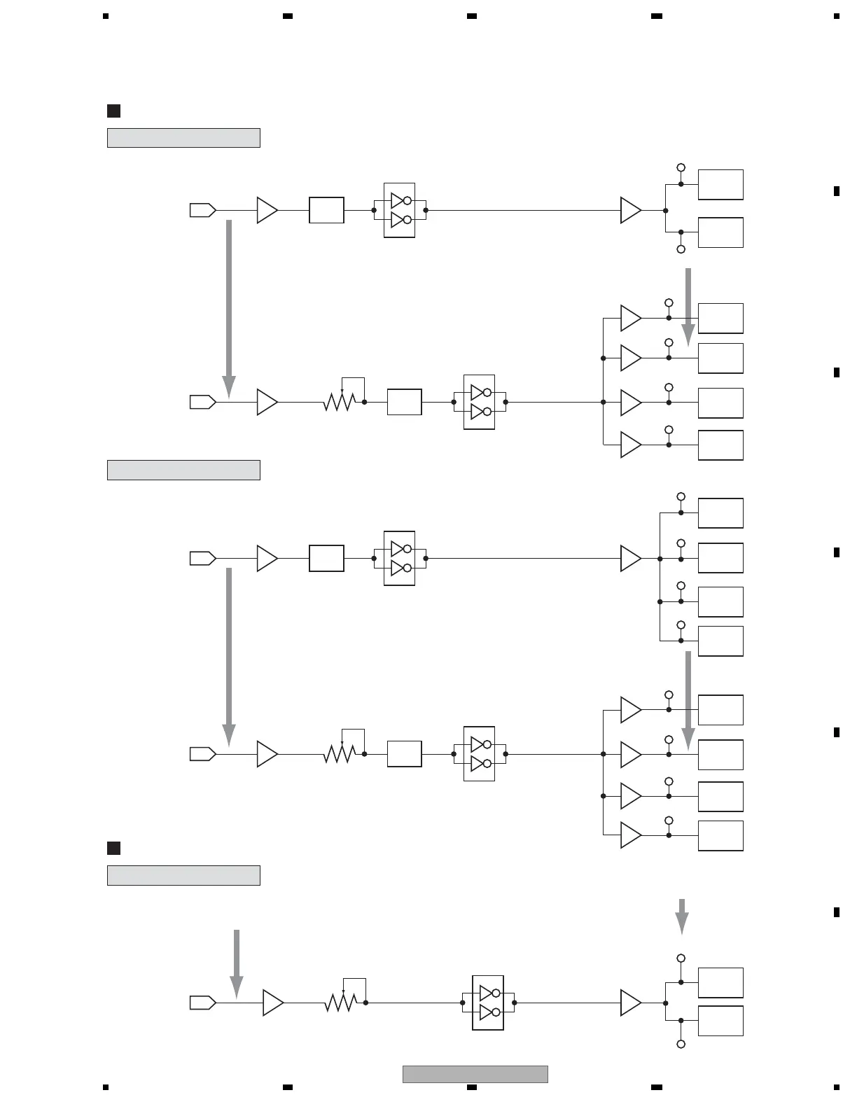
SUS-B ADJUSTMENT
X DRIVE Assy
SUS-D ADJUSTMENT
XSUS-U
from
DIGITAL Assy
IC1002_A1
Pin
2
Pin
2
Pin
8
IC1101
IC1204
IC1104
Q1116
IGBT
Q1104
TP1127
TP2105
Photo
Coupler
Q1108
IGBT
TP1119
Q1219
FET
TP1204
Q1220
FET
TP1205
Q1221
FET
TP1206
1 Measure the SUS-U and SUS-B
input delay time (Δ Tsus - iub).
from
DIGITAL Assy
XSUS-B
IC1001_A1
VR1002
Photo
Coupler
IC1209
Q1205
Q1206
Q1207
2 Adjust the SUS-U and SUS-B input
delay time so that it becomes
"Δ Tsus - iub + 70 ± 5 nsec."
Q1218
FET
TP1258
Q1204
Y DRIVE Assy
Y DRIVE Assy
1 Measure the SUS-D pulse width (Tsus - D).
2 Adjust the pulse width (Tsus - Dg) of the SUS-D
input signal so that it becomes "Tsus-D ± 5 nsec."
from
DIGITAL Assy
YSUS-D
IC2005_A7
Q2105
VR2001
IC2104
Q2111
IGBT
TP2114
Q2113
IGBT
TP2116
YSUS-U
from
DIGITAL Assy
IC2001_A4
Pin
5
IC2101
IC2103
Q2106
IGBT
Q2107
IGBT
Q2104
Photo
Coupler
TP2106
TP2107
Q2108
IGBT
TP2108
Q2109
IGBT
Pin
7
IC2201
Q2217
FET
TP2204
Q2218
FET
TP2205
Q2219
FET
TP2206
1 Measure the SUS-U and SUS-B
input delay time (Δ Tsus - iub).
from
DIGITAL Assy
YSUS-B
IC2001_A6
VR2002
Photo
Coupler
IC2203
Q2204
Q2205
Q2206
2 Adjust the SUS-U and SUS-B input
delay time so that it becomes
"Δ Tsus - iub + 60 ± 5 nsec."
Q2220
FET
TP2207
Q2207

 Loading...