PDP-5071PU
156
1234
1234
C
D
F
A
B
E
8.2.4 INITIALIZE MODE
Operation item
1 SYNC DET(+) Exclusively used for technical analsyis. -
2 SG MODE Paired SG_MODE with SG_PATTERN.
Select SG Route.
-
3 SG PATTERN Paired SG_MODE with SG_PATTERN.
Select SG Pattern.
-
4 SIDE MASK LEVEL(+) Configure the color of the side mask. BSL
GSL
RSL
5 FINAL SETUP(+) Initialize flash memorys on virgin product status FST
6 HMG/HG SERVICE MODE Enter HMG/HG SERVICE MODE -
7 CVT AUTO Exclusively used for technical analsyis. -
8 HDMI INTR POSITION(+) Exclusively used for technical analsyis. -
8.2.4.1 SYNC DET(+)
Exclusively used for technical analsyis (details omitted).
Note : When there is an altered history due to an open TRAP SW, if the "DISPLAY" key is held for at least
5 seconds on the above menu, the altered history will be cleared and the unit will be back to normal.
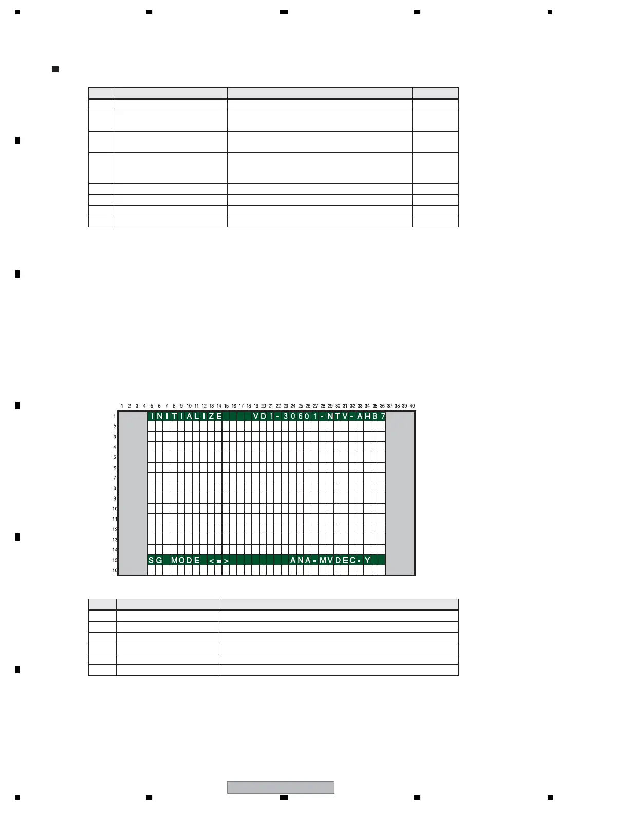
8.2.4.2 SG MODE
SG MODE (SG’s route selection)/SG PATTERN (signal pattern selection) are used as pair.
In SG MODE, select the SG route and then select the SG pattern to be sent by the selected
route. In SG MODE, make sure to select the route first.
1 SG OFF SG Mode is OFF.
2 DIG MVDEC YCBCR MAIN VDEC: YCbCr (Digital output mode)
3 ANA MVDEC YCBCR MAIN VDEC: YCbCr (Analog output mode)
4 ANA MVDEC Y MAIN VDEC: Y (Analog output mode: SG VDEC return setting)
5 ANA AD YCBCR AD: YCbCr
6 ANA AD RGB AD: RGB
No. Display Content RS232C
No. Display Content
 Loading...