PDP-5071PU
218
1234
1234
C
D
F
A
B
E
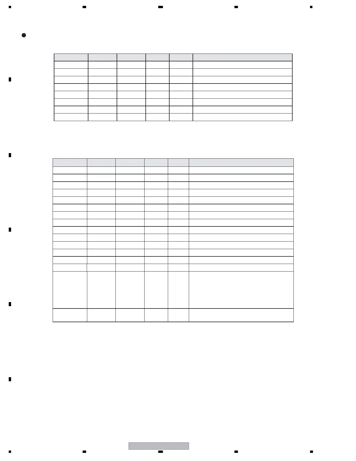
Digital Audio Output Pins
XTALIN 97 — LVTTL In Crystal Clock Input.
XTALOUT 96 — LVTTL Out Crystal Clock Output.
MCLKOUT 88 8 mA LVTTL Out Audio Master Clock Output.
SCK 86 4 mA LVTTL Out I
2
S Serial Clock Output.
WS 85 4 mA LVTTL Out I
2
S Word Select Output.
SD0 84 4 mA LVTTL Out I
2
S Serial Data Output.
SPDIF 78 4 mA LVTTL Out S/PDIF Audio Output.
MUTEOUT 77 4 mA LVTTL Out Mute Audio Output.
Configuration/Programming Pins
INT 104 4 mA LVTTL
1
Out Interrupt Output
RESET# 102 — Schmitt In Reset Pin. Active LOW. 5V Tolerant.
DSCL0 32 — Schmitt In DDC I
2
C Clock for Port 0. 5V Tolerant.
DSDA0 31 4 mA Schmitt Bi-Di DDC I
2
C Data for Port 0. 5V Tolerant.
DSCL1 30 — Schmitt In DDC I
2
C Clock for Port 1. 5V Tolerant.
DSDA1 29 4 mA Schmitt Bi-Di DDC I
2
C Data for Port 1. 5V Tolerant.
CSCL 28 — Schmitt In Configuration I
2
C Clock. 5V Tolerant.
CSDA 27 4 mA Schmitt Bi-Di Configuration I
2
C Data. 5V Tolerant.
SCDT 103 12 mA LVTTL Out Indicates active video at HDMI input port.
CLK48B 107 12 mA LVTTL Bi-Di Data Bus Latch Enable.
2
R0PWR5V 34 — Schmitt In Port 0 Transmitter Detect. 5V Tolerant.
R1PWR5V 33 — Schmitt In Port 1 Transmitter Detect. 5V Tolerant.
RSVDL 101 — LVTTL In Reserved, must be tied LOW.
RSVD_A 56 Reserved Pin, leave unconnected.
NC 6,7,8,10,1
1,12,13,1
4,17,18,1
9,20,81,8
2,83,87,9
3,100
——
No internal connection.
EVNODD 9 8 mA LVTTL Out Indicates Even or Odd field for interlaced
formats. Polarity programmable in register.
Pin Name Pin # Strength Type Dir Description
Pin Name Pin # Strength Type Dir Description
Pin Function
Notes:
1. The INT pin is programmable as either a push-pull LVTTL output, or as an open-drain output.
2. CLK48B is used to clock external 24-to-48 bit latches. CLK48B is also latched on the rising edge of RESET# to
set the I2C device addresses for CSCL/CSDA. Refer to Table 10. CLK48B has a weak internal pull-down, and
so will be latched as a LOW if not otherwise connected.
———
—
 Loading...