813
813
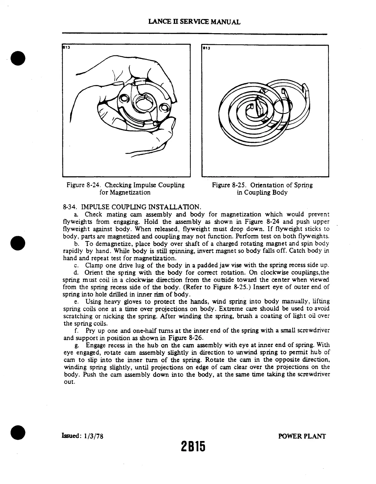
Figure 8-24. Checking
Impulse Coupling Figure
8-25. Orientation of Spring
for Magnetization in Coupling Body
8-34. IMPULSE COUPLING INSTALLATION.
a.
Check mating cam assembly and body
for magnetization which would
prevent
flyweights
from engaging.
Hold the assembly
as shown
in Figure 8-24 and
push upper
flyweight against
body. When released,
flyweight
must drop down. If
flyweight sticks
to
body,
parts are magnetized
and coupling
may not function.
Perform test on both
flyweights.
b. To demagnetize, place
body over shaft of a charged rotating
magnet and spin body
rapidly by hand. While body is still
spinning, invert magnet so body falls
off. Catch body in
hand and repeat test for magnetization.
c.
Clamp one drive lug of the body in
a padded jaw vise with the spring recess
side up.
d.
Orient the spring with the body for
correct rotation. On clockwise couplings,the
spring must coil in a clockwise
direction from the outside toward
the center when viewed
from the spring
recess side of the body. (Refer to
Figure 8-25.) Insert eye of outer end
of
spring into hole drilled
in inner rim
of body.
e. Using
heavy gloves to
protect the hands,
wind spring into
body manually, lifting
spring
coils one at a
time over projections
on body. Extreme
care should be
used to avoid
scratching or
nicking the spring.
After winding the
spring, brush a coating
of light oil over
the spring coils.
f. Pry
up one and one-half
turns at the inner
end of the spring
with a small screwdriver
and support
in position as
shown in Figure 8-26.
g. Engage recess
in the hub on the
cam assembly with
eye at inner end
of spring. With
eye engaged, rotate
cam assembly slightly in direction to
unwind spring to permit hub of
cam to slip
into the inner turn
of the spring.
Rotate the cam in
the opposite direction,
winding spring slightly, until projections on edge of cam clear over the projections on the
body. Push
the cam assembly
down into the body,
at the same time
taking the screwdriver
out.
Issued:
1/3/78
POWER
PLANT
2B15
LANCE
II SERVICE
MANUAL