EasyManuals Logo

Piper Lance II User Manual

Piper Lance II
568 pages
To Next Page IconTo Next Page
To Previous Page IconTo Previous Page
Page #438 background imageLoading...
Page #438 background image
LANCE
II
SERVICE
MANUAL
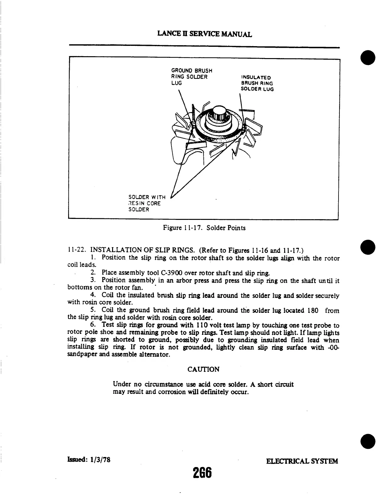
GROUND
BRUSH
RING
SOLDER
LUG
INSULATED
BRUSH
RING
SOLDER
LUG
SOLDER
WITH
RESIN
CORE
SOLDER
Figure
1 1-17.
Solder
Points
11-22.
INSTALLATION
OF
SLIP
RINGS.
(Refer
to
Figures
11-16
and
11-17.)
1.
Position
the
slip
ring
on
the
rotor
shaft
so
the solder
lugs
align
with
the
rotor
coil
leads.
2.
Place
assembly
tool
C-3900
over
rotor
shaft
and
slip
ring.
3.
Position
assembly
in
an arbor
press
and
press
the
slip
ring
on
the
shaft
until
it
bottoms
on
the
rotor
fan.
4.
Coil
the
insulated
brush
slip
ring
lead
around
the
solder
lug
and
solder
securely
with
rosin
core
solder.
5.
Coil
the
ground
brush
ring
field
lead
around
the
solder
lug
located
180
from
the
slip
ring
lug
and
solder
with
rosin
core
solder.
6.
Test
slip
rings
for
ground
with
110
volt
test
lamp
by
touching
one
test
probe
to
rotor
pole
shoe
and
remaining
probe
to slip
rings.
Test
lamp
should
not
light.
If
lamp
lights
slip
rings
are
shorted
to
ground,
possibly
due
to
grounding
insulated
field
lead
when
installing
slip
ring.
If
rotor
is not
grounded,
lightly
clean
slip
ring
surface
with
-00-
sandpaper
and
assemble
alternator.
CAUTION
Under
no
circumstance
use
acid
core
solder.
A
short
circuit
may
result
and
corrosion
will
definitely
occur.
Issued:
1/3/78
ELECTRICAL
SYSTEM
266

Table of Contents

Questions and Answers:

Question and Answer IconNeed help?

Do you have a question about the Piper Lance II and is the answer not in the manual?

Piper Lance II Specifications

General IconGeneral
ManufacturerPiper Aircraft
Max Takeoff Weight3, 600 lb (1, 633 kg)
Crew1
Horsepower300 hp
Seats6
Length27 ft 7 in (8.41 m)
Capacity5 passengers

Related product manuals