LANCE
II SERVICE
MANUAL
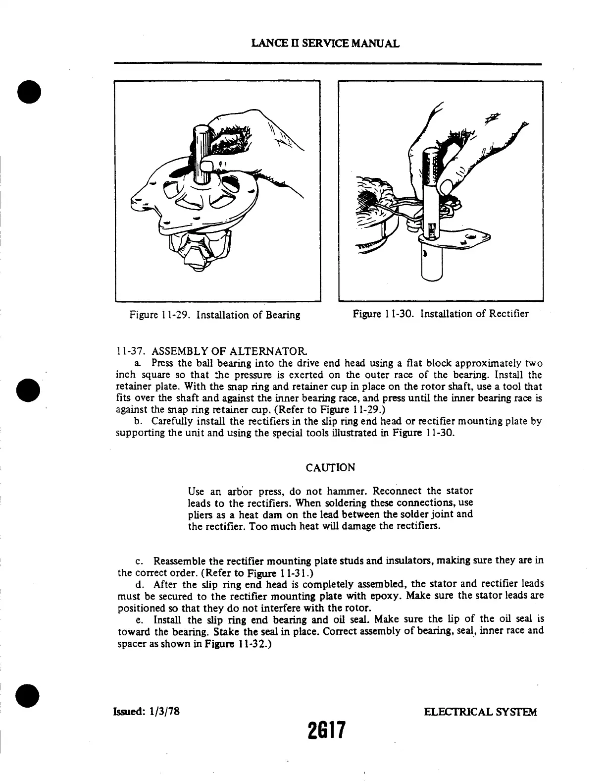
Figure
11-29.
Installation
of Bearing
Figure
11-30.
Installation
of Rectifier
11-37.
ASSEMBLY
OF ALTERNATOR
a. Press the ball bearing into the drive end head using a flat block approximately two
inch square so that the pressure
is exerted on the outer race of the
bearing. Install the
retainer plate.
With the snap ring and retainer cup
in place on the rotor shaft, use a tool
that
fits over the shaft and against
the inner bearing race, and press until
the inner bearing race is
against the snap ring retainer cup. (Refer to Figure 1 1-29.)
b. Carefully install the rectifiers in the slip ring end head or rectifier mounting plate by
supporting the unit and using the special tools illustrated in Figure 11-30.
CAUTION
Use an
arbor press,
do
not hammer.
Reconnect
the stator
leads to
the rectifiers.
When soldering
these
connections,
use
pliers as a heat
dam on the lead between
the solder joint and
the rectifier. Too much heat will damage the rectifiers.
c. Reassemble
the rectifier mounting
plate studs
and insulators, making
sure they are
in
the correct
order. (Refer
to Figure 1 1-31.)
d. After the slip
ring end head is
completely assembled,
the stator and
rectifier leads
must be secured to
the rectifier mounting
plate with epoxy.
Make sure the
stator leads are
positioned so that they
do not interfere with
the rotor.
e. Install
the slip
ring end bearing
and oil
seal. Make
sure the
lip of the oil
seal is
toward
the bearing.
Stake the seal
in place. Correct
assembly
of bearing,
seal, inner
race and
spacer as shown in Figure 11-32.)
Issued:
1/3/78
ELECTRICAL
SYSTEM
2G17