EasyManuals Logo

Piper Lance II User Manual

Piper Lance II
568 pages
To Next Page IconTo Next Page
To Previous Page IconTo Previous Page
Page #461 background imageLoading...
Page #461 background image
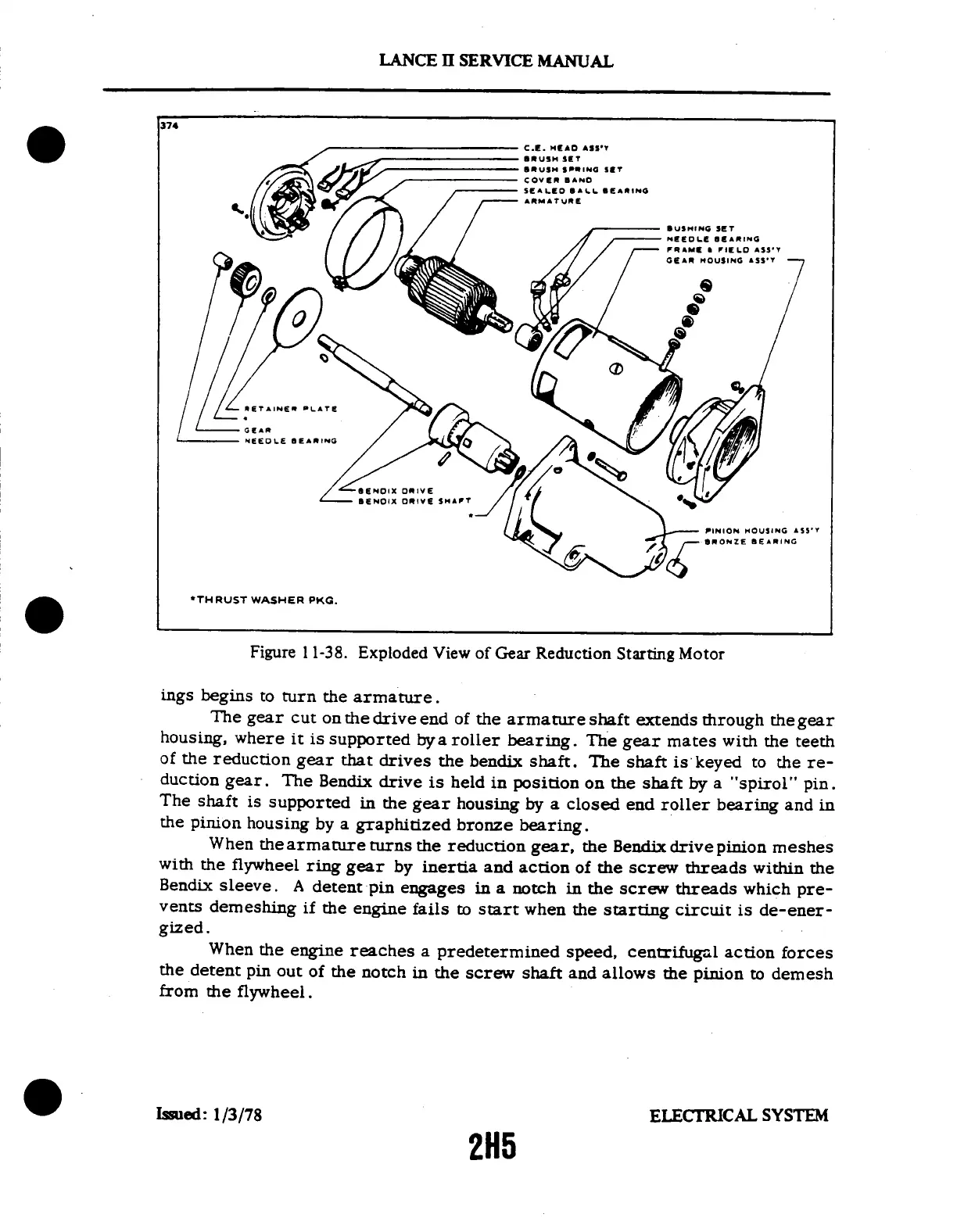
374
*THRUST
WASHER
PKG.
Figure
1
1-38.
Exploded
View
of
Gear
Reduction
Starting
Motor
ings
begins
to
turn
the
armature.
The
gear
cut
on
the
drive
end
of
the
armature
shaft
extends
through
the
gear
housing,
where
it
is
supported
bya
roller
bearing.
The
gear
mates
with
the
teeth
of
the
reduction
gear
that
drives
the
bendix
shaft.
The
shaft
is
keyed
to
the
re-
duction
gear.
The
Bendix
drive
is
held
in position
on
the
shaft
by
a
"spirol"
pin.
The
shaft
is
supported
in
the
gear
housing
by
a
closed
end
roller
bearing
and
in
the
pinion
housing
by
a
graphitized
bronze
bearing.
When
the
armature
turns
the
reduction
gear,
the
Bendix
drive
pinion
meshes
with
the
flywheel
ring
gear
by
inertia
and
action
of
the
screw
threads
within
the
Bendix
sleeve.
A
detent
pin
engages
in
a notch
in
the
screw
threads
which
pre-
vents
demeshing
if
the
engine
fails
to
start
when
the
starting
circuit
is
de-ener-
gized.
When
the
engine
reaches
a
predetermined
speed,
centrifugal
action
forces
the
detent
pin
out
of
the
notch
in
the
screw
shaft
and
allows
the
pinion
to
demesh
from
the
flywheel.
Issued:
1/3/78
ELECTRICAL
SYSTEM
2H5
LANCE
II SERVICE
MANUAL

Table of Contents

Questions and Answers:

Question and Answer IconNeed help?

Do you have a question about the Piper Lance II and is the answer not in the manual?

Piper Lance II Specifications

General IconGeneral
ManufacturerPiper Aircraft
Max Takeoff Weight3, 600 lb (1, 633 kg)
Crew1
Horsepower300 hp
Seats6
Length27 ft 7 in (8.41 m)
Capacity5 passengers

Related product manuals