Slide the component with the T piece from the rear of the cabin forwards. The end of this
component will be pulled through the left hole in the firewall (when looking at the motor
from the rudder) and connected to the smaller T junction in the engine bay. Examine the
component and quickly determine which of the two silicon tubes is longer. Place the
component so that the longer piece is on the right side of the cabin and the shorter piece
is on the left (when looking at the motor from the rudder).
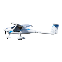
The fuel return line can then be pulled under the cabin floor and through the right hand
hole in the firewall. It then follows the already-placed fuel line towards the left wing. Be
sure to cover the ends of all fuel hoses with masking tape to protect them from dust
when going through the fuselage. Furthermore make sure they are clear of all controls
and the trimmer cables. Feed them towards the left side of the aircraft, in the back the
blue hose goes beneath all the other cables and control lines.
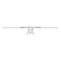
T piece and fuel return line, behind
the cabin
Check to make sure that there is no excessive freeplay in the lines and they do not cross
any control cables where they may get worn.
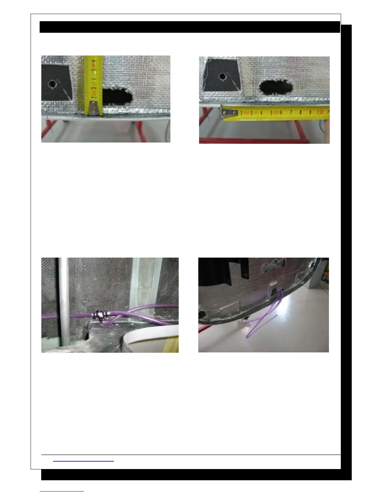
Preparing the engine bay:
Grind the surface of the fuselage lip a little to ensure it is flat and then drill a hole in the
fuselage lip as shown in the photo below. Fix the fuel filler/drain valve to the lip and be
sure to apply Loctite 577 to both sets of threads on either end of the fuel filler/drain
valve. The valve should open and close to the left and, if need be, slightly grind the
http://www.pipistrel.si © Pipistrel Release March 2009 © Page 50 of 267