NOTE
Milling-tool T11 (2.5mm/RADIUS PMMA/WAX) must be available.
For more information, see section "Registering tools in control
software" on page 54 and the
Planmeca PlanMill 50 S user's
manual
.
5. Start the milling process, click the START icon:
Milling unit starts the calibration body milling. Wait until the milling
process is completed.
8. Open the lid and remove the workpiece.
9. Close the Remote DENTAL.
10. Loose the milled calibration bodies from the workpiece.
11. Continue in the TK-Zero_Point dialog and click Next button.
11.5.3 Measuring zero point and B-axis calibration body
Three points must be measured on the both milled calibration bodies to
perform the zero point and B-axis calibration.
Tools required
Thickness gauge with an accuracy of at least 0.01 mm.
Measuring calibration body
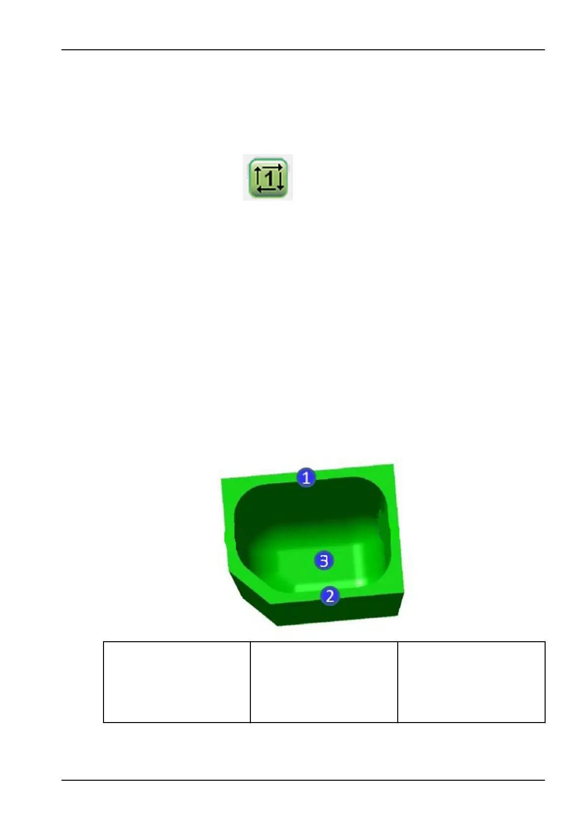
In the following figure, the individual measuring points needed to measure
are marked with number 1, 2 and 3.
1. Wall thickness in the Y-long
direction:
Using the thickness gauge
measure the wall thickness of
the Y-long wall in the middle of
the wall.
2. Wall thickness in the Y-short
direction:
Using the thickness gauge
measure the wall thickness of
the Y-short wall in in the middle
of the wall.
3. Wall thickness in the Z-top:
Using the thickness gauge
measure the wall thickness in
the Z-top wall in the middle of
the plate.
11 Preventive maintenance
User's manual Planmeca PlanMill 50 S 93