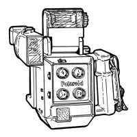
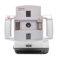
Home
Polaroid
Digital Camera
Macro 5 SLR
Polaroid Macro 5 SLR Repair Manual
4
of 1
of 1 rating
83 pages
Give review
Manual
Specs
To Next Page
To Next Page
To Previous Page
To Previous Page
Loading...
Repair Manual
Macro 5 SLR Camera
37
Required Tools and Equipment
•
Pencil Soldering Iron
•
Solder Sucker
•
Anti-Static Mat and Wrist Strap
•
Standard Tool Kit
•
Torx Driver (6" Apex
Torx T-10 Tip)
•
Small Pair of Diagonal Cutters
•
Cleaning T
issue or Soft Clean Rags
•
Universal PLCC Extraction Tool (fits 20-84 pin Micro Controller)
36
38
Table of Contents
Repair Manual
2
Table of Contents
2
Purpose of this Manual
3
Organization of this Manual
3
Other Documents Required for Service
3
List of Illustrations
4
Section 1. Camera Description
6
Important Safety Instructions
7
Figure 1-1 Macro 5 SLR Camera
8
General
8
Features
9
Camera
9
Figure 1-2 Macro 5 SLR Features
10
Figure 1-3 Control Panel
14
Specifications
18
Section 2. Theory of Operation
20
Figure 2-1 Camera Setup
23
Figure 2-2 Picture Taking
26
Section 3. Adjustments
27
Figure 3-1 Camera Test Fixture
28
Figure 3-2 Range Light Adjustment
29
Figure 3-3 Range Light Adjustments
30
Figure 3-4 Grid Position
31
Figure 3-5 Grid Adjustments
32
Section 4. Troubleshooting
33
Section 5. Parts Replacement
35
Required Tools and Equipment
37
Disassembly/Assembly of Camera
38
Electrostatic Discharge Warning
38
Inspection and Cleaning
38
Left/Right Cover (Includes Front Cover)
39
Removal (Figure 5-1, 5-2 and 5-2A)
39
Figure 5-1 Camera Disassembly
40
Figure 5-2 Left/Right Bottom Screw Location
41
Figure 5-2A Trigger Cables
41
Reassembly
42
Figure 5-3 Front Cover
43
Front Cover
43
Removal (Figure 5-3)
43
Reassembly
44
Figure 5-4 Rear Cover
45
Rear Cover
45
Removal (Figures 5-2 and 5-4)
45
Reassembly
46
Figure 5-5 Bottom Cover
47
Bottom Cover
47
Removal (Figure 5-5)
47
Reassembly
48
Figure 5-6 Strobe PC Board
49
Removal (Figure 5-6)
49
Reassembly
50
Strobe PC Board
49
Removal (Figure 5-7)
51
Trigger PC Boards
51
Figure 5-7 Trigger PC Boards
52
Reassembly
52
Figure 5-8 S1/S2 PC Board
53
Figure 6-1 S1/S2 PC Board
53
Removal (Figure 5-8)
53
Reassembly
54
Figure 5-9 Control Panel
55
S1/S2 PC Board
53
Control Panel
55
Removal (Figure 5-9)
55
Reassembly
56
Logic PC Board
57
Removal (Figure 5-10)
57
Figure 5-10 Logic PC Board
58
Reassembly
58
Camera Back
59
Removal (Figure 5-11)
59
Figure 5-11 Camera Back
60
Reassembly
60
Figure 5-12 Encoder Plate and Lower Turret Plate
62
Encoder Plate and PC Board
62
Removal (Figure 5-12 and 5-12A)
62
Figure 5-12A Encoder PC Board
63
Reassembly
64
Figure 5-13 Turret Assembly
65
Removal (Figure 5-13)
65
Reassembly
66
Figure 5-14 Shutter Solenoid Assembly
67
Turret Assembly
65
Removal (Figure 5-14)
67
Reassembly
68
Figure 5-15 Aim Light Cable Assembly
69
Shutter Solenoid Assembly
67
Bulb (Aim Light) Bracket Assembly
69
Removal (Figure 5-15)
69
Reassembly
70
Figure 5-16 Date Code Module
71
Date Code Module
71
Removal (Figure 5-16)
71
Reassembly
72
Firmware (Logic PC Board)
73
Removal (Figure 5-17)
73
Figure 5-17 Firmware CPU
74
Reassembly
74
Section 6. Schematics
75
Figure 6-2 Encoder PC Board
77
Figure 6-3 Trigger PC Board
78
Figure 6-4 Strobe PC Board (1 of 2)
79
Figure 6-5 Strobe PC Board (2 of 2)
80
Figure 6-6 Logic PC Board (1 of 2)
81
Figure 6-7 Logic PC Board (1 of 2)
82
Figure 6-8 Communication PC Board
83
Other manuals for Polaroid Macro 5 SLR
User Guide
14 pages
4
Based on 1 rating
Ask a question
Give review
Questions and Answers:
Need help?
Do you have a question about the Polaroid Macro 5 SLR and is the answer not in the manual?
Ask a question
Polaroid Macro 5 SLR Specifications
General
Brand
Polaroid
Model
Macro 5 SLR
Category
Digital Camera
Language
English
Related product manuals
A500 - 5.1MP Digital Camera
44 pages
Polaroid M737T
119 pages
Polaroid m630, m635
97 pages
Polaroid MiniPortrait 203
19 pages
Polaroid Miniportrait 485B
31 pages
Polaroid Snap
12 pages
Polaroid PIC 300
2 pages
Polaroid Snap Touch
46 pages
Polaroid DIGITAL 320
19 pages
Polaroid OneStep SX-70
21 pages
Polaroid impulse series
11 pages
Polaroid Digital Camera
67 pages