Repair Manual
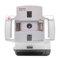
Macro 5 SLR Camera
73
Firmware (Logic PC Board)
Notes: • Use a dump stick to fully discharge the strobe capacitors before
attempting to remove or replace the system firmware (CPU chip).
• The CPU chip can easily be damaged by static discharges.
Always use an anti-static mat and a wrist-strap when removing or
replacing it.
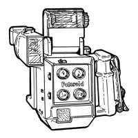
1. Removal (Figure 5-17)
a. Remove the left/right cover assembly as explained on page 39.
b. Remove the rear cover assembly as explained on page 45.
c. Remove the control panel as explained on page 55.
d. Locate the CPU on the logic PC board. Observe its orientation in its
socket - dot and beveled corner faces top of logic PC board.
e. Insert the fingers of the chip puller into the provided slots at the top right
and bottom left corners of the socket.
f. Remove the CPU by gently but firmly squeezing the handles of the chip
puller together.
Caution: Shock Hazard - High Voltage
 Loading...