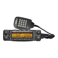
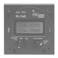
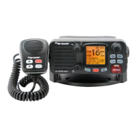
◊ Microphone
NO. KEY FUNCTION
1 UP
Increase frequency,channel number or
setting value.
2 DOWN
Decrease frequency, channel number or
setting value.
3 PTT
Press the PTT (Push-To-Talk) key to
transmit.
4 Number Key Input VFO frequency or DTMF dial out etc.
5 A/B band
Choose left band or right band as Main
band.
6 Band indicator The indicator light on for Main band.
7 TX/RX indicator
Light green while receiving, Light red while
transmitting.
8 MIC Speak here during transmission.
9 Speaker
When shut the speaker in the base, you
can hear the calling by this speaker.
MIC Connector Diagram (in the front view of connector).
13
1
2
3
5
6
7
8
4
DN
UP
1
4
78
9
0
#
5
6
2
3
PA
MIC
PB
A
B
A
A/B
B
PC
PD
MAIN
Key Pad Serial Data
+5V
DOWN
UP
MIC GND
MIC
PTT
GND