EasyManuals Logo

Polytec MSA-600 User Manual

Polytec MSA-600
99 pages
To Next Page IconTo Next Page
To Previous Page IconTo Previous Page
Page #28 background imageLoading...
Page #28 background image
3-4
3 First Steps
3.2 Control Elements, Displays, and Connections
3.2.1 Sensor Head
Back view
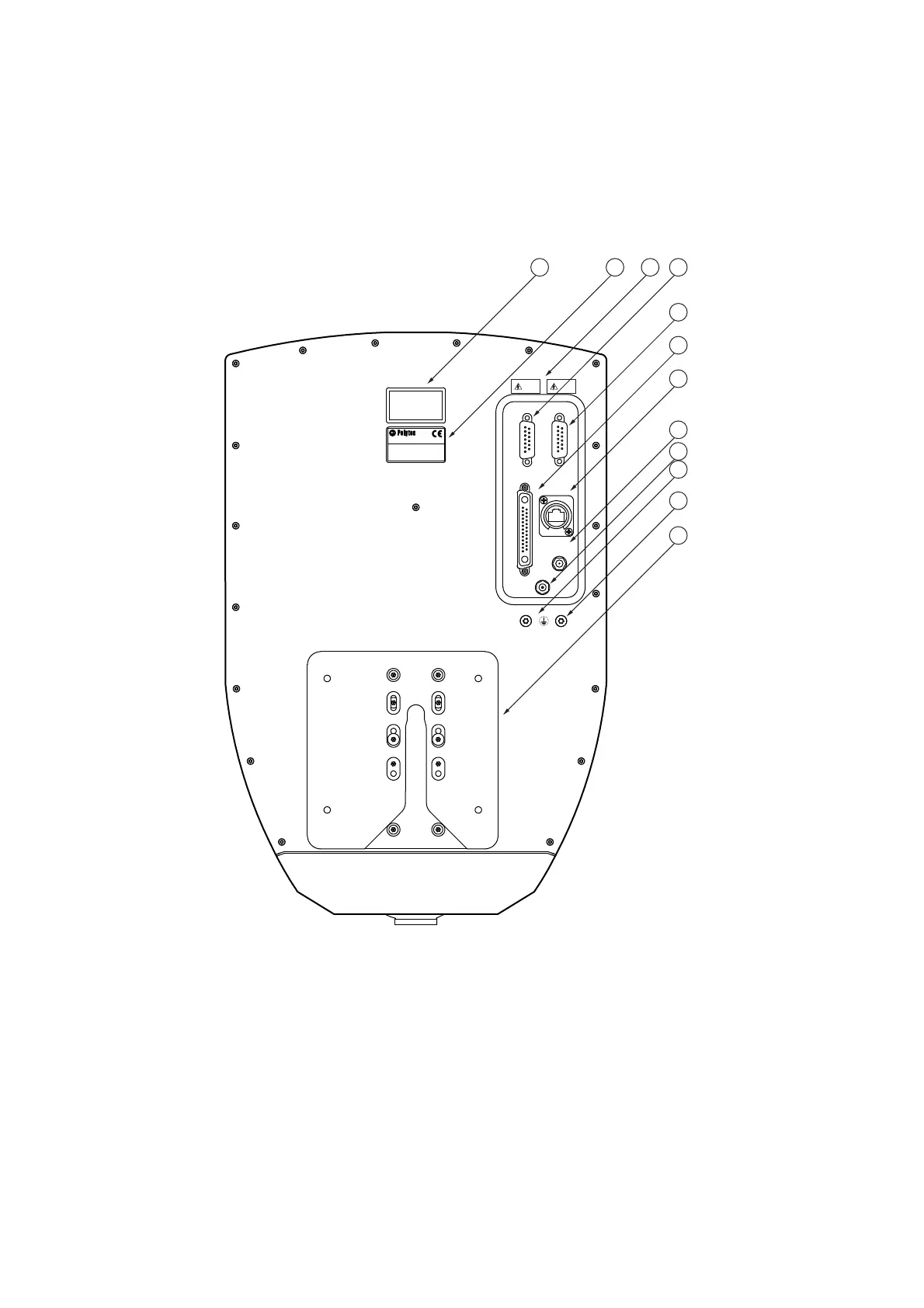
The back view of the sensor head is shown in the following figure.
Figure 3.1: Back view of the sensor head
1
Warning label
2
Name plate
3
Warning label (residual voltage)
4 SCANNER
connection (15-pin Sub-D jack)
5 REF SCANNER
connection (15-pin Sub-D jack)
6SYSTEM
main connection (25-pin Sub-D jack)



"DIUVOH
3FTUTQBOOVOH
"UUFOUJPO
3FTJEVBM7PMUBHF
"DIUVOH
3FTUTQBOOVOH
"UUFOUJPO
3FTJEVBM7PMUBHF
%&
9,'(2
5()6&$11(5
6&$11(5
6<67(0
3RO\WHF*PE+3RO\WHF3ODW]
':DOGEURQQ*HUPDQ\
5)287

Table of Contents

Questions and Answers:

Question and Answer IconNeed help?

Do you have a question about the Polytec MSA-600 and is the answer not in the manual?

Polytec MSA-600 Specifications

General IconGeneral
BrandPolytec
ModelMSA-600
CategoryMeasuring Instruments
LanguageEnglish

Related product manuals