3-7
3 First Steps
3.2.3 Controller
INFORMATION
Depending on which option the MSA-600 is supplied with, the controller
equipment and therefore the look of the back can vary.
Back view
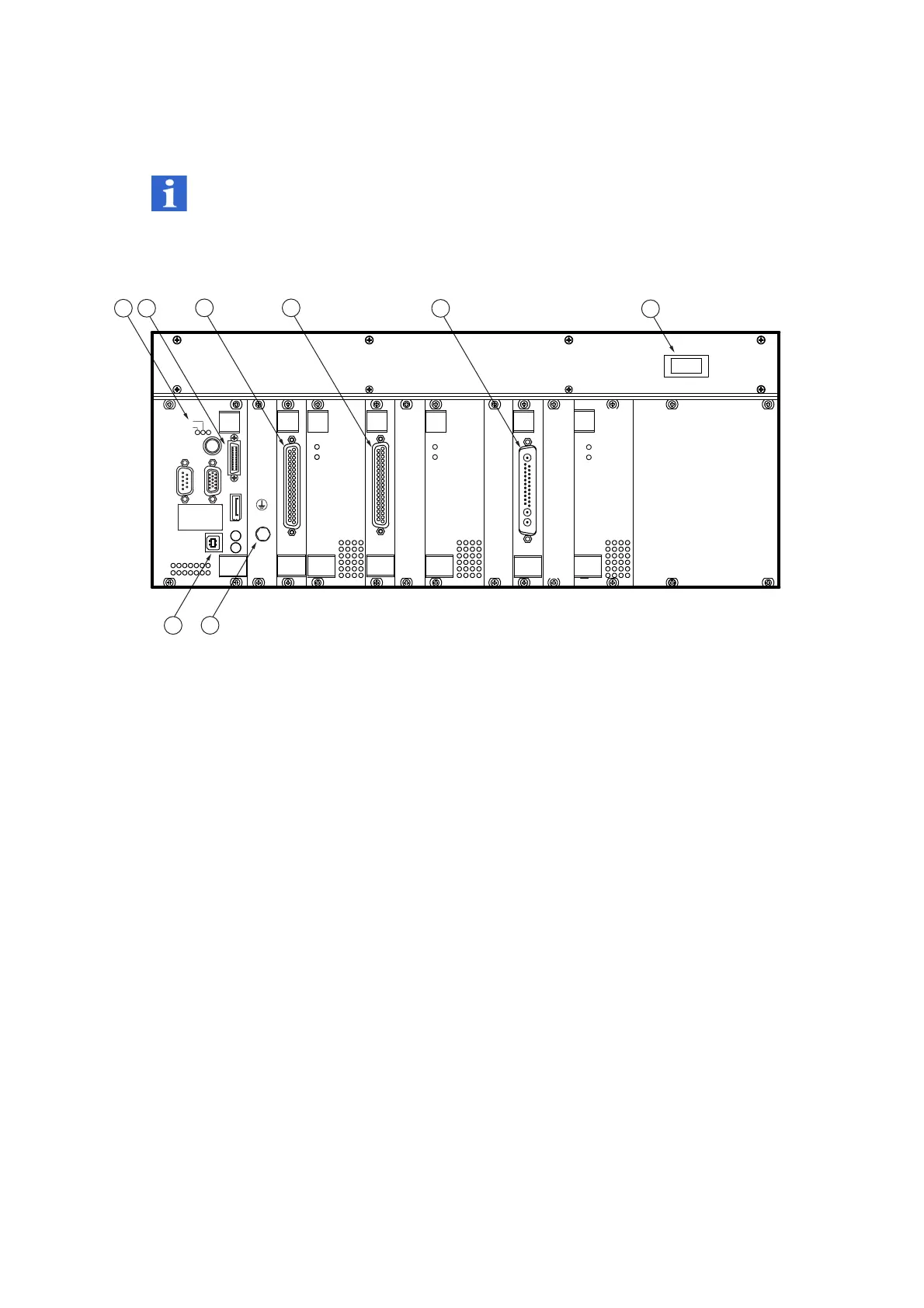
The back view of the controller is shown in the following figure.
Figure 3.4: Back view of the controller
1 POWER/ERROR
status display
2 DIGITAL I/O
connection (20-pin MDR plug-in connector)
3 SCANNER
connection (37-pin Sub-D jack)
4 REF SCANNER
connection (37-pin Sub-D jack)
5 OBJECTIVE POSITIONER
connection (25-pin Sub-D plug-in connector for mixed
contacts)
6I/O
mains switch
7
Connector for the protective earth cable to the sensor head
8
USB connection (Universal Serial Bus, type B)
32:(5
(5525
6&$11(5
5()6&$11(5
2%-(&7,9(326,7,21(5
3:5
29(5
7(03
3:5
29(5
7(03
3:5
29(5
7(03
',*,7$/,2
,
2