3-6
3 First Steps
Back view
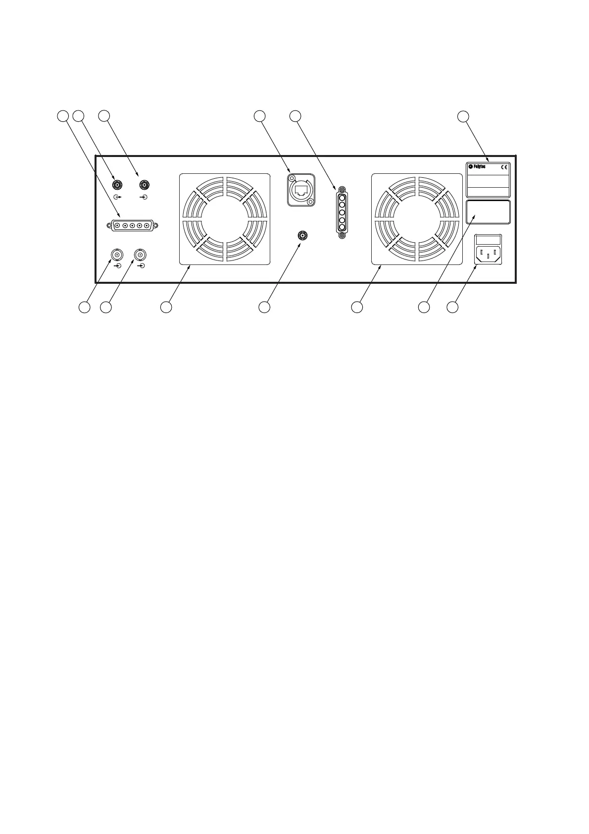
The back view of the front-end is shown in the following figure.
Figure 3.3: Back view of the front-end
1 ACQ/GEN
connection (Sub-D jack)
2REF
connection (SMA jack)
3SIGNAL
connection (SMA jack)
4 CONTROL
network connection (marked in yellow)
5SYSTEM
main connection (Sub-D jack)
6
Name plate
7POWER
mains connection (socket for standard power cord with built-in fuses)
8
Warning label
9
Cooling fan
10 BC
connection (SMA jack)
11 TRIG TMS
connection (BNC jack)
12 TRIG AF
connection (BNC jack)
Connection for the A-CTR-1x0 Axis Controller (refer to separate operating
instructions)
5()
6,*1$/
$&4*(1
&21752/
32:(5
75,*$)
75,*706
$&+781*
9RUGHPgIIQHQ
1HW]VWHFNHU]LHKHQ
:$51,1*
'LVFRQQHFW0DLQV
EHIRUHRSHQLQJ
6<67(0
%&
3RO\WHF*PE+3RO\WHF3ODW]
':DOGEURQQ*HUPDQ\