Do you have a question about the powertronics PQR D52 and is the answer not in the manual?
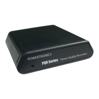
Identifies PowerTronics, the PQR Series, Model D52, and provides contact information.
States copyright year and reserves the right to make changes without notice.
Warns about ungrounded outlets and high voltage inside the cabinet.
Lists Channel, Temperature & Humidity, Operating, Mechanical, and Interface specifications.
Defines common power problems like Dropout, Sag, Impulse, Noise, Surge, and Frequency.
Details the warranty period, what is covered, and exclusions for material and workmanship defects.
Outlines steps for returning a product for repair, including contacting customer service.
Explains the PQR D52's function in interpreting AC power line problems and its applications.
Describes plugging the unit into a power outlet to start testing.
Details the high accuracy of measurements, annual calibration recommendation, procedure duration, and fees.
Highlights user-friendliness, multiple phase monitoring, fast impulse detection, and ease of reports.
Mentions the PQR Host Communications Software for data download, display, and printing.
Describes how data collection begins upon power application and continues until unplugged.
Explains sampling voltage every minute and storing up to 32,000 readings for up to 20 days.
Explains the function of the status LED during diagnostics and operational status.
Describes the unit going on-line after diagnostics and recommended testing duration.
Details connecting via USB port, driver availability, and required cable.
Explains RS232 connection, pinout, null modem cable requirement, and baud rate settings.
Lists software capabilities: auto-connect, configure, download, and generate reports/charts.
Presents an example of a Time History Plot of AC1 and T1 data from a data log report.
Instructions for downloading from website or using provided disk to install the software.
Details the initial steps of the installation program, including closing other applications.
Explains how to choose or create a program group for the installed software.
Describes how to launch the PowerTronics Host Interface Software after installation.
Details how to open, close, and print data files stored on disk.
Describes tracking recent files and how to exit the software.
Explains how to toggle the visibility of the toolbar and status bar.
Allows selection of the computer's COM port for device communication.
Provides an interface to set the device's internal date and time.
Allows the user to specify the data rate for device communication.
Allows selection of the interval between data logging samples (e.g., 1 sec, 1 min).
Configures thresholds for surge, sag, and power failure events.
Lists options for retrieving data: Data Log, Detail Report, Summary Report, Calibration Mode, Clear Data.
Shows a status window indicating the progress of data download.
Process for downloading voltage measurements and opening the data window.
Describes the format of the text report showing date, time, voltage, temperature, and humidity.
Allows selection of 1 or 2 channels (Hot, Neu, Temp, Hum) to graph.
Shows a time history plot of temperature and humidity data.
Displays a time history plot of hot line voltage over a period.
Explains how to create a selection box for zooming and double-clicking to reset the view.
Process for downloading disturbance details and opening the data window.
Describes event details: date, time, phase, event type, and magnitude.
Process for downloading disturbance counts and opening the data window.
Allows generation of a pie chart showing the distribution of detected events.
Describes entering calibration mode to transmit voltage readings and how to stop transmission.
Explains how to clear all events and data log information from the device's memory.
Lists commands available for communication via serial port using terminal emulator software.
Details how to issue command C0 or 'CONNECT' to display the command list.
Shows the available command options displayed by the PQR D52.
Describes issuing command C1 to transmit the model name and version number.
Explains that the version number refers to firmware and is needed for technical support.
Details issuing command C2 to transmit a count of detected disturbances.
Explains report format and how to terminate transmission using the Escape character.
Details issuing command C3 to transmit the detailed report of all saved disturbances.
Describes event details and how to terminate transmission using the Escape character.
Details issuing command C4 to transmit voltage measurements on all input channels.
Explains the header and line format of the data log, indicating minute or hourly readings.
Details issuing command C5 to clear all events and data log information.
Explains the confirmation prompt ('Y') and the RAM clear operation.
Details issuing command C6 to access the setup options menu.
Shows the current settings for date/time, baud rate, logging rate, and thresholds.
Explains how to select option 1 and input the date and time.
Specifies the required MM/DD/YY, HH:MM:SS format including commas, slashes, and colons.
Details selecting option 2 to change the communications baud rate.
Notes that the terminal rate must match the device rate and settings are saved in FLASH RAM.
Details selecting option 3 to change the interval between data logger readings.
States that the new setting is saved in Non-Volatile RAM and is the power up default.
Allows changing threshold points for events like surge, sag, and power failure.
Demonstrates setting the Temperature Surge threshold to 98 degrees.
Details issuing command C90 to view voltage and line frequency on channels and neutral.
Explains its use for confirming connections and how to exit the mode.
Describes issuing command CX to disconnect the signal from a phone line modem.
Details AC RMS Voltage range, accuracy, sample rate, and input channels.
Specifies thresholds, duration limits, and accuracy for various disturbance types.
Details specifications for impulse (spike/surge) and high frequency noise measurements.
Details range, accuracy, response time, and threshold for line frequency.
Details the range, accuracy, and sample rate for optional temperature logging.
Details the range, accuracy, and sample rate for optional humidity logging.
Covers temperature, humidity, voltage, current, weight, and size.
Details USB port, RS232 port, Baud Rate, and Protocol settings.
Introduces common power disturbances and their effects on equipment.
Provides a visual representation of a standard AC waveform.
Defines a dropout as a portion of the sine wave with a lower or missing value.
Defines a power failure as a dropout exceeding one cycle, also known as a blackout.
Explains sag as a decrease in line voltage and its common causes like inductive loads.
Defines impulse as a short-duration energy surge on the AC line, potentially damaging.
Explains voltage induced onto the neutral line by other equipment, appearing as impulses or sine waves.
Defines surge as an increase in line voltage above normal, often caused by inductive loads.
Explains noise from electronic equipment or switching supplies causing disturbances on the AC line.
Highlights suitability for Single, Dual, Three Phase, and Environmental applications.
Mentions the range from simple PQR D50 to sophisticated PQR 1010.
Lists the types of disturbances the PQR D50 measures, including spikes, sags, and power failures.
Describes simple operation, event storage in FLASH RAM, and data logging capacity.
Highlights multi-channel AC/DC voltage, current, humidity, temperature, and voltage logging.
Describes connection, power, and the included graphics software for reports.
Lists features like user-friendly, programmable, multiple phase monitoring, and fast impulse detection.
States its use as a state-of-the-art instrument for AC power quality analysis.
Highlights measuring all disturbance types and simple operation with LCD display.
Includes testing Temperature, Ground line, DC Voltage, and rugged carrying case for D300.
Emphasizes full function, low cost, ease of use, and understanding power problems.
Generates reports to understand causes of power problems and guide protection decisions.
Measures common-mode noise, spikes, surges, sags, power failures, and dropouts.
Describes simple operation, LED indication of worst-case power problems, and event storage.
| Model | PQR D52 |
|---|---|
| Category | Measuring Instruments |
| Measurement Range | 0-600V AC |
| Accuracy | ±0.5% |
| Display | LCD |
| Power Supply | 9V battery |