Different from ordinary digital quantity input terminals, virtual VDI state can have two
setting modes which is selected by E3.06.
When selecting VDI state is determined by the state of the corresponding virtual VDO, VDI
is valid or invalid state depending on the VDO output valid or invalid, and VDIx only binding
VDOx(x=1~5).
When choosing VDI state selection function code to set, through the binary bits of E3.05,
respectively determine the state of virtual input terminals.
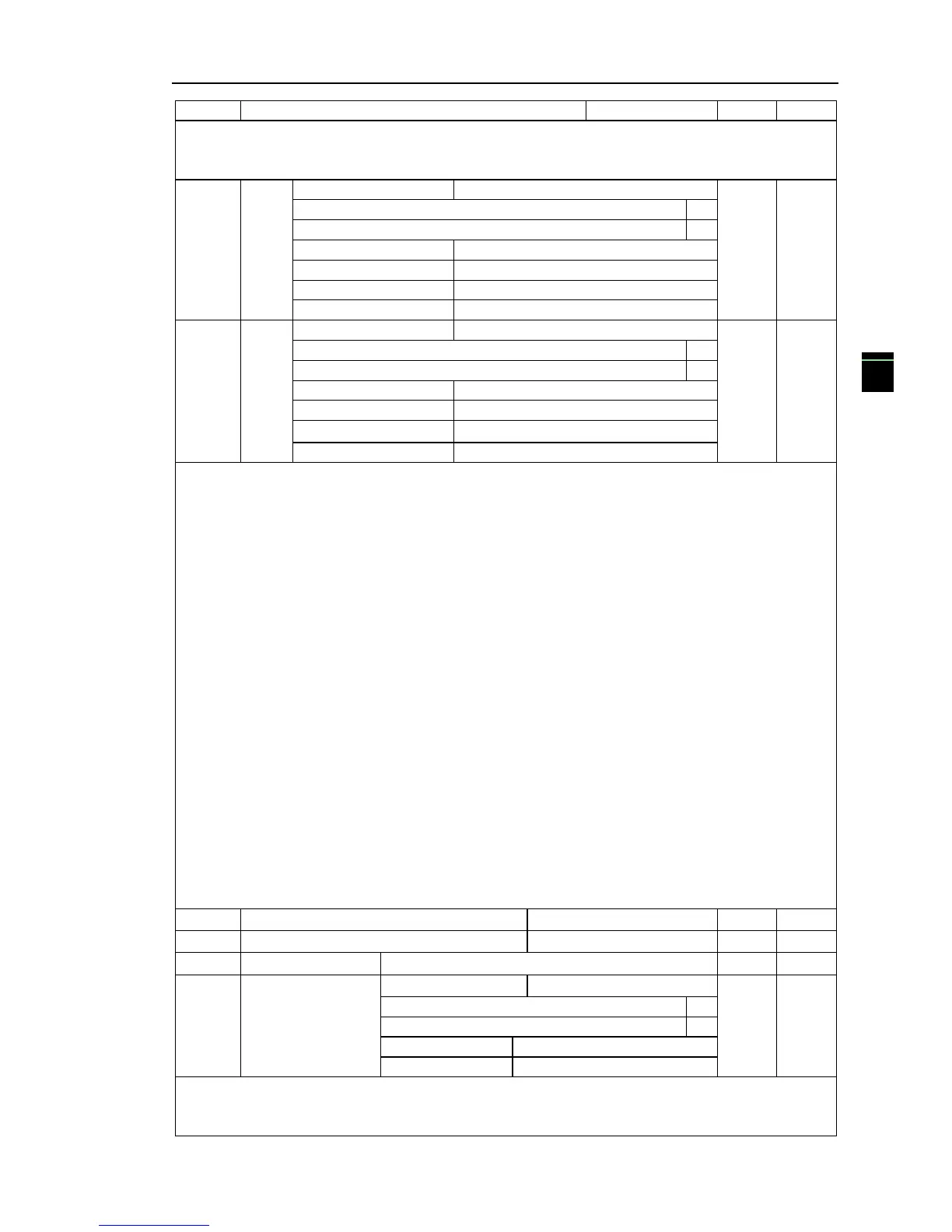
Example of how to use VDI.
Example 1. Implement following function: “Inverter fault alarm and shuts down when AI1
input exceeds upper or lower frequency” .
Realize by following settings: Set VDI state decided by VDO, set VDI1 function as “ user
defined fault 1” (E3.00=44); set VDI1 terminal state effective mode decided by VDO1
(E3.06=xxx0); set VDO1 output function as “AI1 input exceeds upper & lower frequency”
(E3.11=31); so when AI1 input exceeds upper or lower frequency, VDO1 state is ON, VDI1 input
terminal state is effective, VDI1 receive user defined fault 1, inverter then alarm fault no. 27 and
shuts down.
Example 2. Implement following function: “Inverter run automatically after power-on”.
Realize by following settings: set VDI state decided by function code E3.05, set VDI1
function as “FORWARD” (E3.00=1); set VDI1 terminal state effective decided by function code
(E3.06=xxx1); set VDI1 terminal state is effective (E3.05=xxx1); set command source as “terminal
control” (F0.11=1); set protection selection as “no protection” (F7.22=0); so after inverter powered
on and initialization complete, VDI1 detected effective, and it match forward running, then
inverter starts running forwardly.
This group function code is used when using AI as DI, when AI used as DI, and input voltage
of AI is greater than 7V, AI terminal status will be high level, when input voltage of AI is lower
than 3V, AI terminal status will be low level. For between 3V~ 7V hysteresis E3.10 is to determine

 Loading...


