Chapter 5 Function parameter
114
that when the AI is used as DI, AI is made valid by means of the high level state, or the low level
of valid states. As for AI as DI feature set, same as the ordinary DI Settings, please refer to the F1
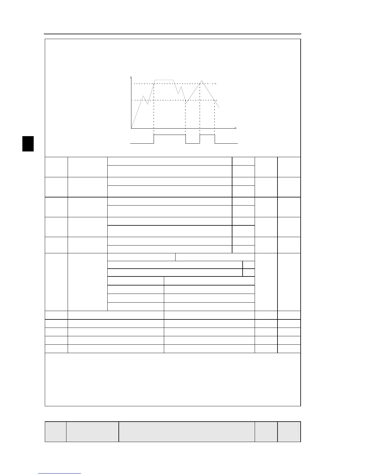
group setting instructions related DI. Below figure is AI input voltage taken as an example,
explains the relationship between input voltage of AI and the corresponding state of DI:
DC7V
Time(t)
AI input
voltage
ON
AI terminal state
DC3V
ON
OFF
Diagram 5-35:Judgment of effective state of AI
With the physical internal sub DIx
See F2 group physical DO output option
With the physical internal sub DIx
See F2 group physical DO output option
With the physical internal sub DIx
See F2 group physical DO output option
With the physical internal sub DIx
See F2 group physical DO output option
With the physical internal sub DIx
See F2 group physical DO output option
VDO output
effective
status
VDO2(0 to 1,same as above)
VDO3(0 to 1,same as above)
VDO4(0 to 1,same as above)
VDO5(0 to 1,same as above)
VDO and DO output function is similar,can be used in conjunction with VDIx,to achieve
some simple logic control .
When VDOx output function is 0, output status is decided by DI1~DI5 input status on the
control board, VDOx and Dix one-to-one correspondence.
When the output function selection is not 0, VD0x function setting and using method is same
as D0 in F2 output parameter, please read F2 group parameter description.
The VDOx output valid status can be set by E3.16 setting, select positive logic or anti-logic.
5-2-19.Motor parameters: b0.00-b0.35

 Loading...


