Chapter 4 Installation and commissioning
21
4-5.Control circuit terminals
4-5-1.Control circuit terminals arrangement
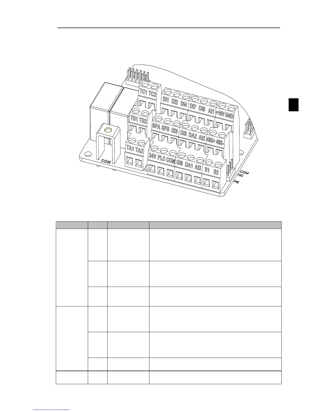
1. Control panel control circuit terminals
Diagram 4-13:Control panel control circuit terminals
4-5-2.Description of control circuit terminals
Output +10V power supply, maximum output current:
10mA
Generally it is used as power supply of external
potentiometer, potentiometer resistance range: 1kΩ to
5kΩ
Output +24V power supply, generally it is used as power
supply of digital input and output terminals and external
sensor.
Maximum output current: 200mA
External power
input terminal
When external signal is used to drive, please unplug PLC
jumpers , PLC must be connected to external power
supply, and to +24V (default).
1.Input range:(DC 0V to 10V/0 to 20mA), depends on
the selected AI1 jumper on control panel.
2.Input impedance: 20kΩ with voltage input, 510Ω with
current input.
1.Input range:(DC 0V to 10V/0to 20mA), depends on the
selected AI2 jumper on control panel.
2.Input impedance: 20kΩ with voltage input, 510Ω with
current input.
1, Input range:DC-10V~+10V
2, Input voltage 20kΩ
Multi-function
digital input 1
1.Opto-coupler isolation, compatible with bipolar input,
Jump line PLC selection decisions;

 Loading...


