Chapter 4 Installation and commissioning
22
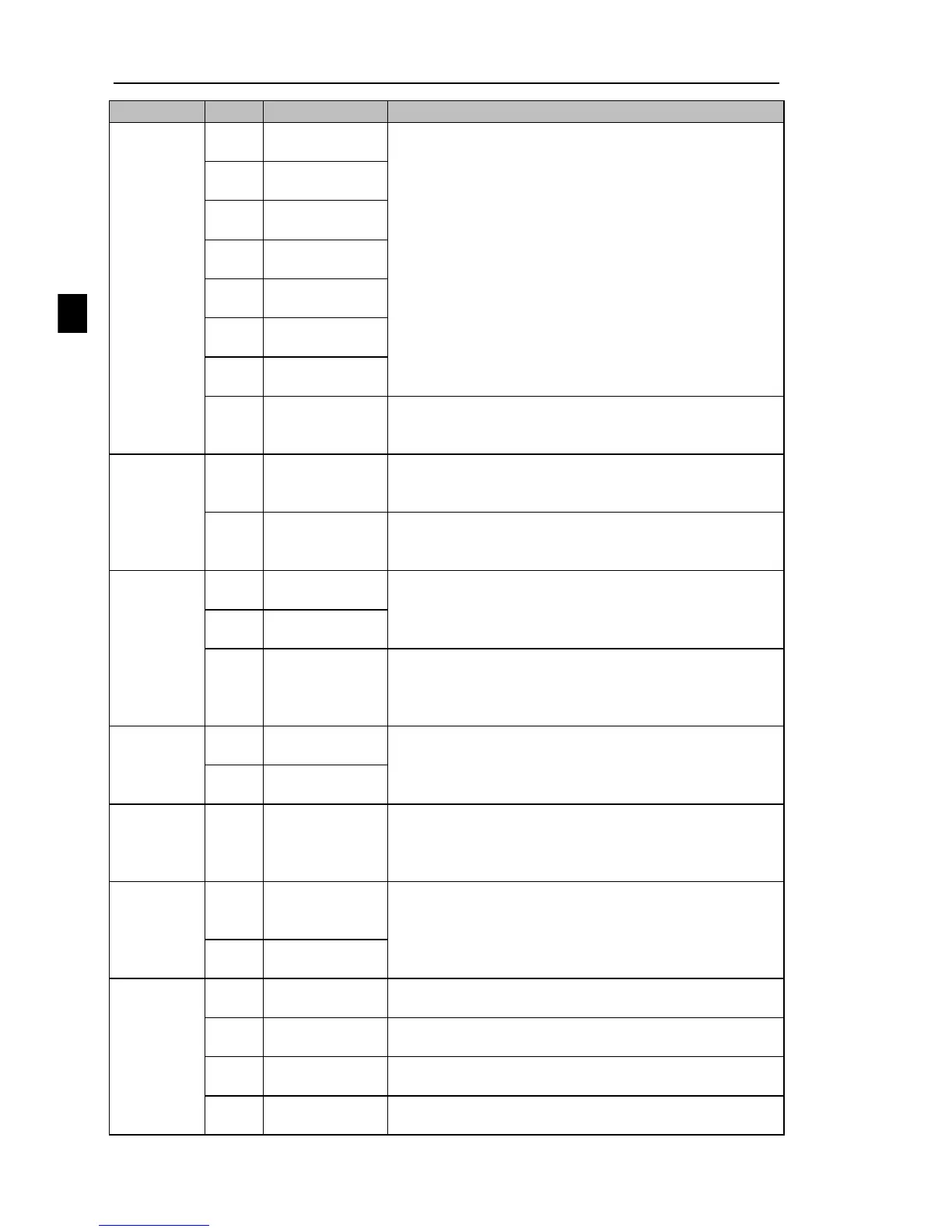
Multi-function
digital input 2
2.Input impedance: 4.7kΩ
3.Voltage range with level input: 19.2V to 28.8V;input
impedance 3.3kΩ
Multi-function
digital input 3
Multi-function
digital input 4
Multi-function
digital input 5
Multi-function
digital input 6
Multi-function
digital input 7
Multi-function
digital input 8
High-speed
pulse input
terminals
Except the function of DI1 to DI4,DI6 to DI8,DI5 can
also be used as high-speed pulse input
channels.Maximum input frequency: 100kHz
The selected DA1 jumper on control panel determines
voltage or current output. Output voltage range: 0V to
10V , output current range: 0mA to 20mA
The selected DA2 jumper on control panel determines
voltage or current output. Output voltage range: 0V to
10V , output current range: 0mA to 20mA
Opto-coupler isolation, bipolar open collector output
Output voltage range: 0V to 24V , output current range:
0mA to 50mA
Subject to function code(F2.00)"SPB terminal output
mode selection"
As a high-speed pulse output, the highest frequency up to
100kHz;
Contactor drive capacity: normally closed contact 3A/AC
250V,normally open contact 5 A/AC 250V, COSø =
0.4.
Normally closed
terminals
Motor
temperature
inspection
input
485 differential
signal +
terminal
485 communication interface, 485 differential signal
terminal, use twisted-pair or shielded wire connect to the
standard 485 communication interface
485 jump line in the control panel to decide whether to
connect the terminal resistance
485 differential
signal - terminal
CAN card, 26-pin terminal
GND jump line decide whether to connect PE, improve
the inverter anti-interference
COM jump line decide whether to connect PE, improve
the inverter anti-interference

 Loading...


