Chapter 4 Installation and commissioning
23
Consistent with the COM function on the terminal line。
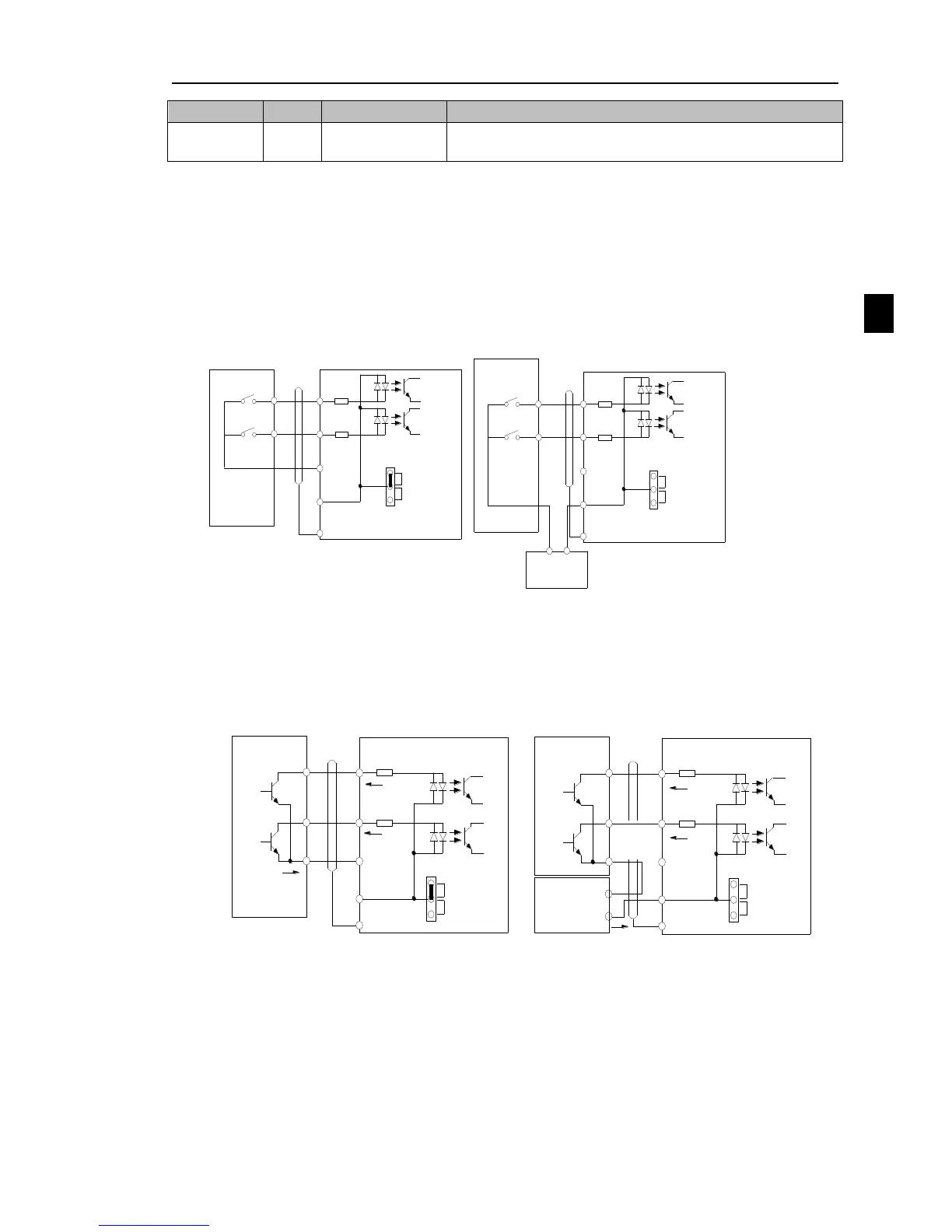
Signal input terminal circuit
Switch input and output signal transmission, generally use the shielded cable and wiring short
distance as far as possible, good grounding and shielding layer on the inverter side, try not to over 20
m transmission distance. Drive in active way, elected to the power of crosstalk necessary filtering
measures are taken, generally recommend that choose dry contact control mode.
Wiring control cable should be kept with the main circuit and high voltage lines (such as the
power cord, motor connecting line, relay or contactor) more than 20 cm distance, and to avoid high
voltage lines parallel to and can't be avoided and the high voltage lines cross, the proposal USES
vertical wiring way, in order to prevent the misoperation caused by disturbance frequency converter
Dry contact mode:
+24V
COM
PLC
(Default)
DI1
DI8
COM
PLC
PE
Shielded
cable
External
contactor
Inverter
Inner power supply with main connect
+24V
COM
PLC
(Default)
DI1
DI8
COM
PLC
PE
Shielded
cable
External
contactor
Inverter
External power supply with main connection
External power
supply
+
-
Diagram 4-14:signal input terminal circuit- dry contact mode
Note: using an external power supply, PLC and 24 v jumper cap must be removed, otherwise it
will damage the product.
Open collector NPN connect wire:
When the input signal from the NPN transistor, according to the use of power supply, please
according to the figure + 24 v and PLC jumper cap.
+24V
COM
PLC
(Default)
DI1
DI8
COM
PLC
PE
Shielded
cable
Inverter
Inner power NPN connect mode
External
contactor
+24V
COM
PLC
(Default)
DI1
DI8
COM
PLC
PE
Shielded
cable
Inverter
External power supply NPN connect mode
External
contactor
External
power supply
+
-
Diagram 4-15:Signal input terminal wiring diagram, open collector NPN connection mode
Note: using an external power supply, PLC and 24 v jumper cap must be removed, otherwise
it will damage the product.
Open collector PNP connection mode:

 Loading...


