Appendix II Description on proportion linkage
function
II-1.Function
Proportional linkage master:
Communication address of master =248
Proportional linkage slave:
Communication address of slave =1 to 247
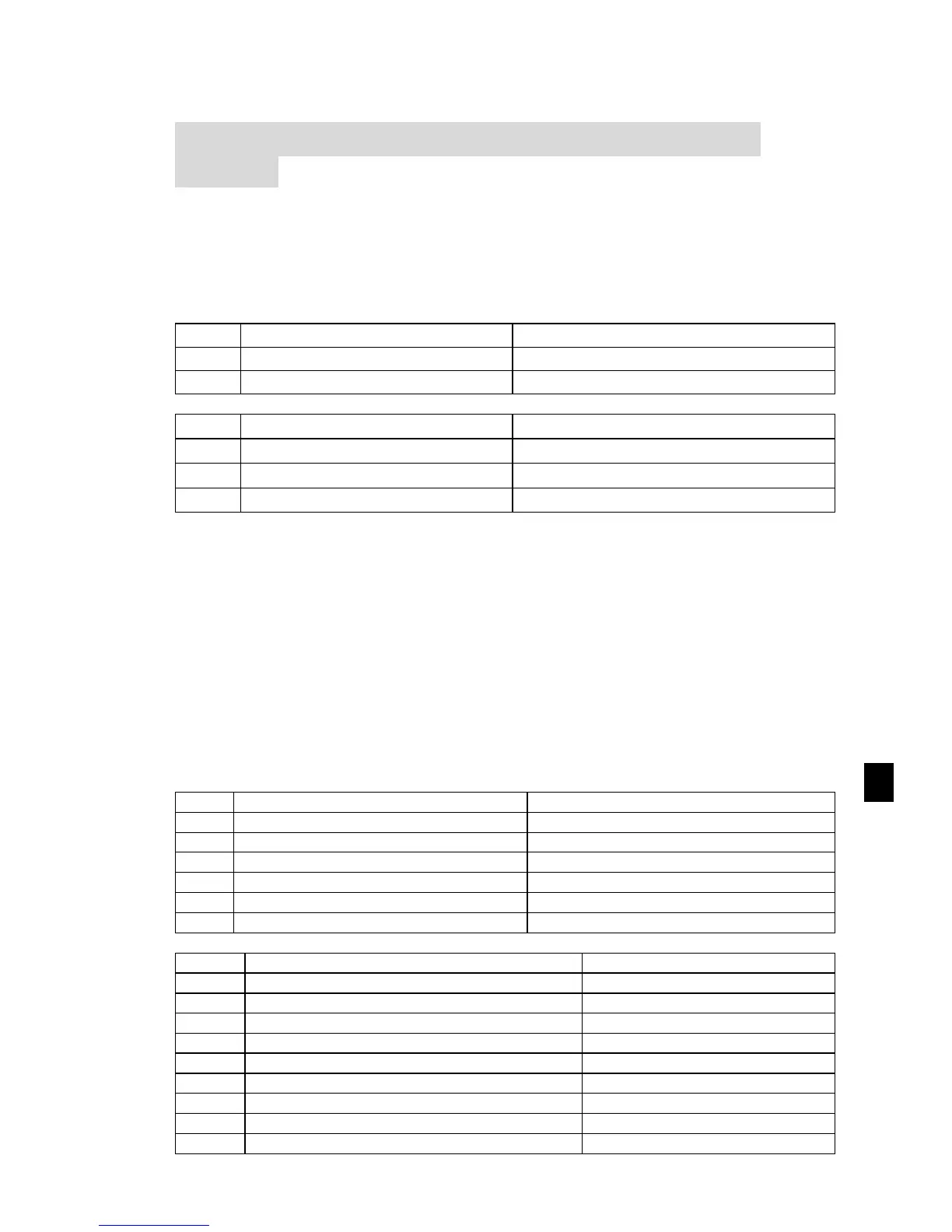
If you want to use proportion linkage function, master parameters setting as follows:
Slave parameters setting as follows
Proportional linkage coefficient
0.00: invalid; 0.01 to 10.00
Slave output frequency = Master setting frequency * Proportional linkage coefficient +
UP/DOWN Changes.
II-2.Examples of proportion linkage function:
Functions provided by proportional linkage system:
1. Master adjusts system speed via AI1 and controls FRW/REV run by using terminals;
2. Slave runs following mater, the proportional linkage coefficient is 0.90; (when it is powered
on, master displays 50Hz, and slave displays 45Hz)
3. Slave receives the running speed command from master and save it into F0.01.
4. The actual setting frequency of slave can be fine-tuned by the operation of rising and falling of
keypad or terminals.
5. The actual setting frequency of slave can be fine-tuned by the analog AI2 too.
6. The actual setting frequency of slave = F0.01 + slave AI2 analog trimming + UP/DOWN
Changes.
Proportional linkage master setting:
1: Terminal block control
Frequency source master setting
DI1 input terminal function selection
DI2 input terminal function selection
Communication address of this unit
Proportional linkage master 248
Proportional linkage slave setting:
Frequency source master setting
0: keyboard set frequency
Frequency source auxiliary setting
Frequency overlay selection
DI1 input terminal function selection
DI2 input terminal function selection
DI3 input terminal function selection
Communication address of this unit
Proportional linkage coefficient

 Loading...


