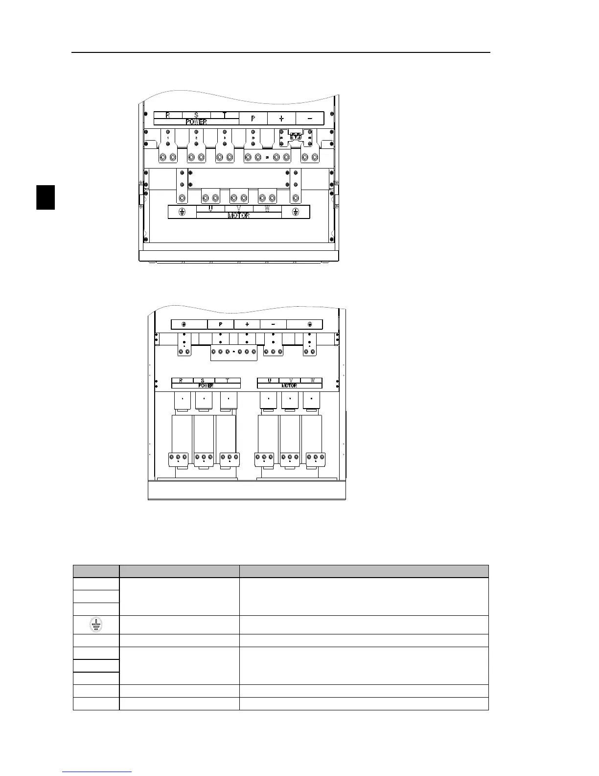
EasyManuals Logo

Powtran PI500 series User Manual

Powtran PI500 series
166 pages
To Next Page IconTo Next Page
To Previous Page IconTo Previous Page
Page #24 background imageLoading...
Page #24 background image
Chapter 4 Installation and commissioning
20
Chapter 4
8.250kW400kW G3 main circuit terminal
Diagram 4-11250kW400kW G3 main circuit terminal
9.450kW~630kW G3 main circuit terminal
Diagram 4-12450kW~630kW G3 main circuit terminal
Note: P/+ standard is circuit standard configuration is for the shorted state; if external DC reactor
is connected, firstly disconnect and then reconnect.
4-4-2.Function description of main circuit terminal
Terminal
Name
Explain
R
Inverter input terminals
Connect to three-phase power supply, single-phase
connects to R, T
S
T
Ground terminals
Connect to ground
P, RB
Braking resistor terminals
Connect to braking resistor
U
Output terminals
Connect to three-phase motor
V
W
+, -
DC bus output terminals
Connect to braking unit
P, +
DC reactor terminals
Connect to DC reactor(remove the shorting block)

Table of Contents

Questions and Answers:

Question and Answer IconNeed help?

Do you have a question about the Powtran PI500 series and is the answer not in the manual?

Powtran PI500 series Specifications

General IconGeneral
BrandPowtran
ModelPI500 series
CategoryDC Drives
LanguageEnglish

Related product manuals