Chapter 5 Function parameter
87
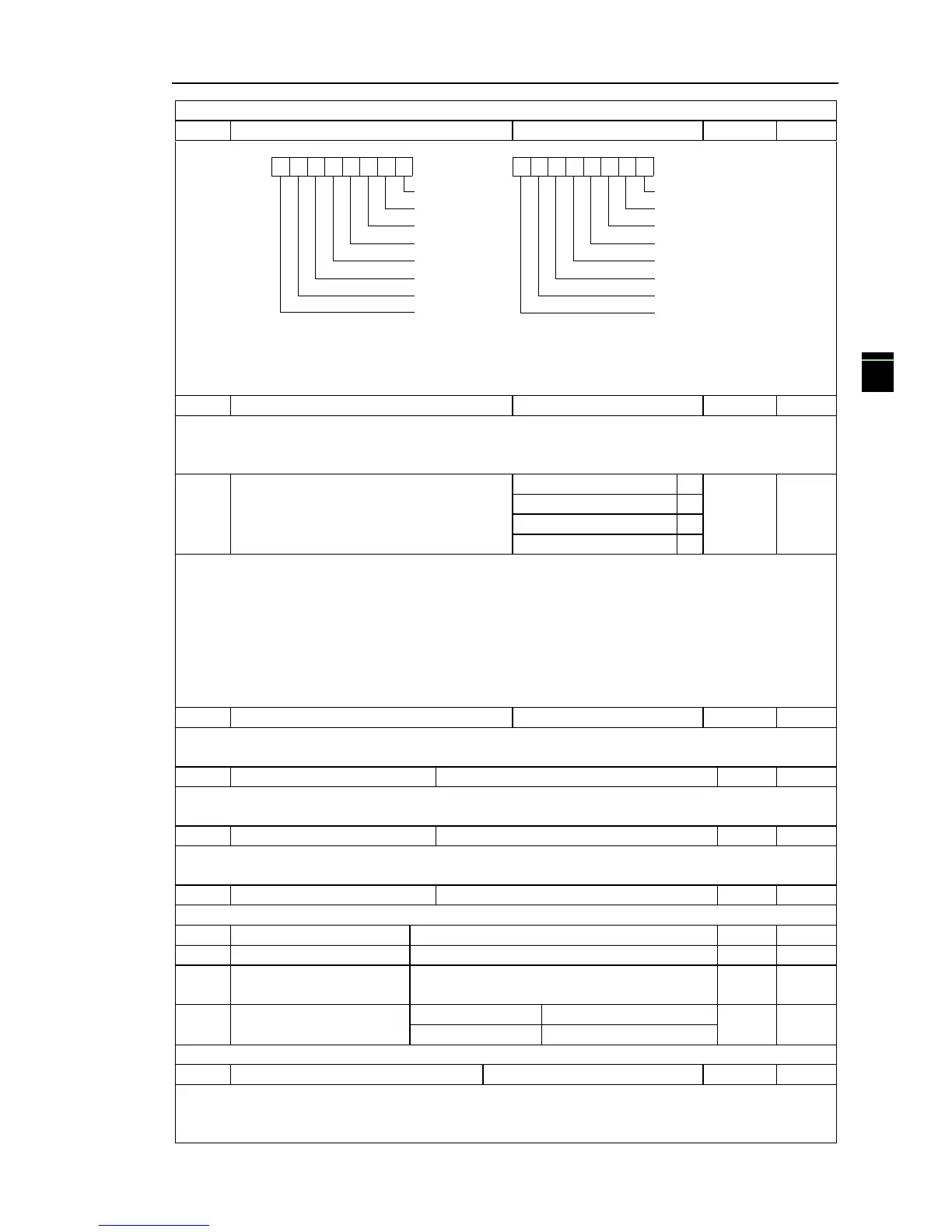
F6.01, F6.02 binary parameter values, the display order starts from the lowest level of F6.01.
Stop status display parameters
0
1
2
3
4
5
6
7
8
910
11
121314
15
DI input situation
Bus voltage
(V)
Setting frequency
DO output situation
AI1 voltage
AI2 voltage
(Hz)
Count value
Remain
Length
Load speed
PID setting
(V)
(V)
PLC range
High speed pulse
input frequency
(Hz)
Remain
Remain
Remain
Diagram 5-17:Stop status
If the above parameters need to be displayed on operation, firstly set its position to 1, and
then set at F6.03 after converting the binary number to the hexadecimal number.
Load speed display coefficient
When load speed needs to be displayed, adjust the inverter's output frequency and load speed
by using the parameter.
Pls refer to the F6.05 for the specific correspondence
Decimal places for load speed display
Decimal places for load speed display The below example illustrates the calculation of load
speed:
If the load speed coefficient(F6.04) is 3.000, the number of decimal places of load
speed(F6.05) is 2 (0 decimal places), when the inverter operating frequency reaches 40.00Hz, the
load speed is : 40.00 * 3.000 = 1200 (0 decimal places display).If the inverter is shutdown, the
load speed displays the speed relative to the set frequency, that is the "set load speed". If the set
frequency is 50.00Hz, the load speed under the state of shutdown: 50.00 * 3.000 = 1500 (0 decimal
places display)
Inverter module radiator temperature
Display the inverter module IGBT temperature.The different models of the inverter module
vary IGBT overtemperature protection values.
Display the total run time of inverter When the run time reaches the set time(F7.21), the
inverter's multi-function digital output function (12) outputs ON signal.
Show the total time of inverter power-on, When the power-on time reaches the set
time(F7.20), the inverter‟s multi-function digital output function(24) outputs ON signal.
Display the total power consumption of inverter to date until now
Control panel software version number
The parameter of motor selection2 can be showed in the bottom of double LED or LCD.
Power correction coefficient
Frequency converter with motor running, the display output power(d0.05)is different with the
actual output power, through the parameters, adjust the converter display power and the actual
output power corresponding relation.

 Loading...


