Chapter 5 Function parameter
94
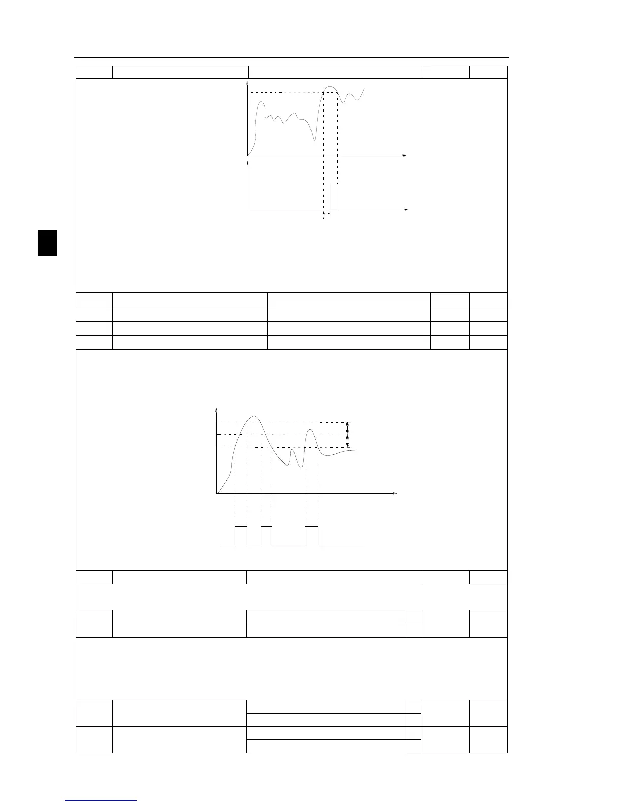
Overrun value of
output current
F7.34
Time(t)
Output current
Output current overrun detection delay time F7.35
Output current
overrun detection
signal
ON
Time(t)
Diagram 5-26:Schematic diagram of output current overrun detection signal
When the inverter's output current is more than or overrun the detection point and lasts for
longer than the delay time of software overcurrent point detection, the inverter's multifunction DO
will output ON signal.
Random arrivals current 1
0.0%~300.0%(rated motor current)
Random arrivals current 1 width
0.0%~300.0%(rated motor current)
Random arrivals current 2
0.0%~300.0%(rated motor current)
Random arrivals current 2 width
0.0%~300.0%(rated motor current)
When the inverter's output current randomly reaches the range of the current detection
width(positive or negative), the inverter multifunction DO will output ON signal.
PI500 provides two group of sets of parameter for Randomly Reaches Current and Detection
Width, the figure is the functional diagram.
Random arrivals current
Time(t)
Output Current
Random arrivals current
detection signal DO orrelay
ON
OFF
ON
OFF
OFF
Random arrivals current width
ON
Random arrivals current width
Diagram 5-27:
Schematic diagram of random arrivals current detection
Module temperature arrival
When the inverter radiator temperature reaches the temperature, the inverter multifunction
DO will output "Module Temperature Arrival" ON signal.
Fan running only when running
Used to select the cooling fan mode, if you select 0, the fan will run when the inverter is
running, but in the stop state of inverter, if the radiator temperature is above 40 degrees, the fan
will run, otherwise the fan will not run.If you select 1, when the fan will always running after
power-on.
Noted: The fan of PI500 will be uncontrolled.
Timing function selection
Timing run time selection

 Loading...


