Chapter 5 Function parameter
39
Frequency 2 reaches
output
Please refer to the function code F7.30, F7.31's
instructions.
Please refer to the function code F7.36, F7.37's
instructions.
Please refer to the function code F7.38, F7.39's
instructions.
When the timer function selection (F7.42) is valid, the
drive time to reach this run after the set time runs out,
output ON signal.
When the value of analog input AI1 greater than F7.51
(AI1 input protection limit) or less than F7.50 (AI1 input
protection under), output ON signal.
When the inverter is off-load state, output ON signal.
Inverter in reverse run, output ON signal
Refer to the description of function code F7.32, F7.33.
Module temperature
reaches
Inverter module heatsink temperature (F6.06) reach the
set module temperature reaches value (F7.40), output
signal ON.
Please refer to the function code F7.34, F7.35's
instructions.
The lower frequency
arrival (stop and output)
When the operating frequency reaches the lower limit
frequency, output ON signal. In shutdown state of the
signal is also ON.
When the inverter failure, and the failure of the process to
continue to run mode, the inverter alarm output.
Motor overtemperature
pre-warning
When the motor temperature reaches F8.35 (motor
overheat pre-alarm threshold), the output ON signal.
(Motor temperature can be viewed at d0.41)
Current running time of
arrival
When the inverter starts running time is longer than the
time set by F7.45, it outputs ON signal.
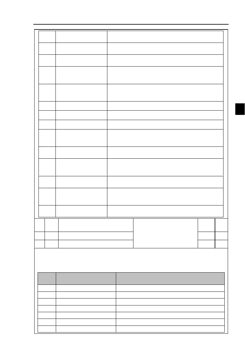
High-speed pulse output function
selection
DA1 output function selection
DA2 output function selection
High-speed pulse output frequency range of 0.01kHz ~ F2.09 (high speed pulse output
maximum frequency), F2.09 can be set between 0.01kHz ~ 100.00kHz.
Analog Output DA1 and DA2 output range is 0V ~ 10V, or 0mA ~ 20mA. Pulse output or
analog output range, with the corresponding scaling function relationship in the following table:
0~2 times the motor rated current
0~2 times the motor rated toqure
0~1.2 times inverter rated voltage

 Loading...