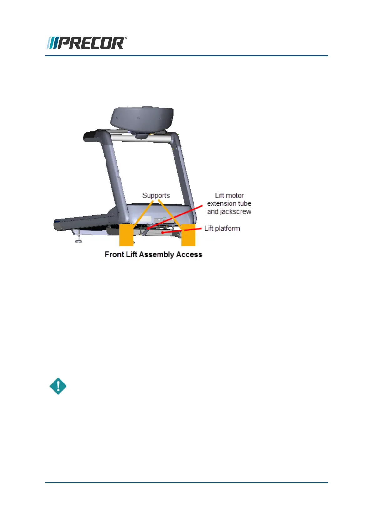
Front lift platform assembly access
This method accesses the lift platform assembly and connected hardware from the front of the
treadmill by raising and supporting the treadmill front frame weldment.
Raising and supporting the treadmill
1. Connect the power cord and switch the input power ON.
2. Access the service menu (51765761) and select INCLINE TEST. Use the incline con-
trol to set the incline level to 14.
3. Securely and safely place supports (e.g. car jack stands) under the left and right front
corners of the frame weldment.
4. Slowly lower the incline level in 0.5 increments setting the frame onto the supports.
Verify the supports are stable carrying the weight of the treadmill and continue lowering
the incline level to "0". Incline level "0" is also the lift motor calibration reference incline
level.
IMPORTANT: It is important to set the incline level to "0" (calibration ref level) before
switching the power OFF.
5. Switch the power OFF and unplug the power cord.
Removing supports and lowering the treadmill
1. .Connect the power cord and switch the power ON. Be aware that switching the power
ON will cause the incline platform to move and return to the level "0" position.
Contact Precor Customer Support at support@precor.com or 800.786.8404 with
any questions.
Page 67
5 Adjustment Procedures
Lift Motor Calibration

 Loading...