562200-000, Issue 1.2, December 2015
49 of 62
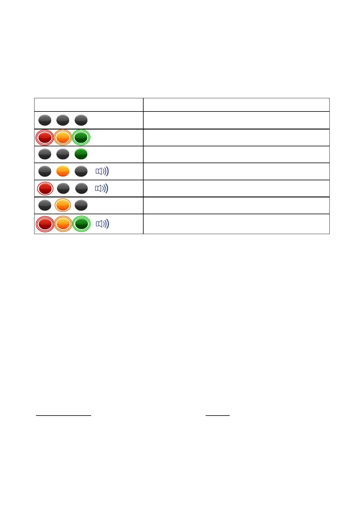
9.2 LED and Internal Alarm Warnings
The table below shows the state of the three LEDs on the display and the internal alarm
with respect to system status.
10 Daily Checks
Display - check for damage and correct operation
Safety Controller - check for damage and correct operation
Sensors and sensor cabling - check for damage
Cable Connections - check for damage, loose or disconnected connectors
Internal / external alarm (if fitted) and beacon (if fitted) functionality
See section 11 for test / diagnosis features.
If an issue is discovered which cannot be rectified using this guide, halt any operation,
seek authorised service immediately and do not continue operation until the fault has
been remedied.
11 Repair
Once a repair has been carried out and tested, the following must be checked:
Required Checks Section
Angles Check 12.2
Relay Check 12.1
Internal / external Alarm, LED and Beacon Check 12.3
Maintenance review 17.1
LED and Internal Alarm status System status
Off
Start up
Operational: System OK, no warnings, hazards, or errors
Warning: Approach to overload or envelope limit
Hazard; Overload or an envelope limit reached
Maintenance: Diagnostics access active
Error: PME hardware/software error, or sensor failure
1 Hz
Continuous
8 Hz