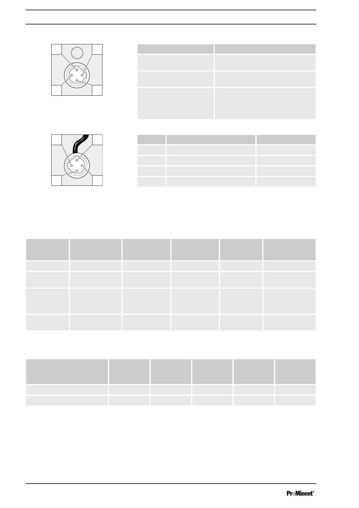
Electrical interface
Specification Value
Supply voltage, approx.: +5 V, loadable with 20 mA (current limit
150 mA)
Power consumption: min. 10 mA, max. 20 mA (sensor pres‐
ence detection)
Sensor signal: potential-free contact (load: 0.5 mA at
+5 V) or
Semiconductor switch (residual voltage
< 0.3 V)
Pin Function 4-wire cable
1 Power supply (5 V) brown
2 not assigned white
3 Sensor signal blue
4 Earth / GND black
9.2.5 Relay
9.2.5.1
Relay functions
gamma/ X GMXa
Identity code Description Type Maximum voltage Maximum cur‐
rent
Behaviour of relay
type when retrofit‐
ting, as standard
0 no relay - - - -
1 Fault indicating
relay
NC changeover
contact
230 V 8 A X
4 fault indicating relay
+
Pacing relay
N/O
N/O
24 V
24 V
100 mA
100 mA
X
X
C fault indicating relay
+ 4-20 mA output
N/O 24 V 100 mA X
Relay type switches in the event of...
Relay type* Level
Warning
Level
low
Dosing monitor
Error
Calibrated
stroke length
Error
Processor
Error
Fault indicating relay: X X X X X
Warning relay: X - - X -
* Can be reprogrammed in the
‘Relay’
menu.
9.2.5.2 "Fault indicating relay" output (identity code 1)
A fault indicating relay can be ordered as an option - refer to ordering
information in the appendix. It is used to emit a signal when there is a fault
with the pump and for the "Liquid level low, 1st stage" warning message
and "Liquid level low, 2nd stage" fault message.
Fig. 20: Pump assignment
Fig. 21: Cable assignment
Installation, Electrical
38
 Loading...