N93-572-88 Issue 12 NH Page 10 of 52 © Protec Fire Detection plc 2020
4.5 Fire Link Wiring
The fire link output may be used to signal an alarm condition to a remote monitoring station.
The fire link output is monitored for open and short circuit cable faults and, when used, must only
connect to the Protec 6100 fire link end of line module. If the fire link output is not used it must be
terminated locally in the panel ( consult section 10.0 for details ).
Suitably fire rated, screened cable must be used to connect the 6100 to the remote end of line
module. The resistance of the cabling must be no more than 25Ω in total ( 12.5Ω per conductor ).
4.6 Addressable Loop Wiring and Devices
The 6100 loop wiring carries both power and data to the loop devices. In order for the system to
operate correctly under all conditions the voltage drop along the loop must be kept within specified
limits.
The voltage drop on the loop is a function of both the resistance of the loop cabling
( determined by the gauge of cable and the length of the loop ) and the current that the loop must carry
( determined by the number and type of loop devices connected ).
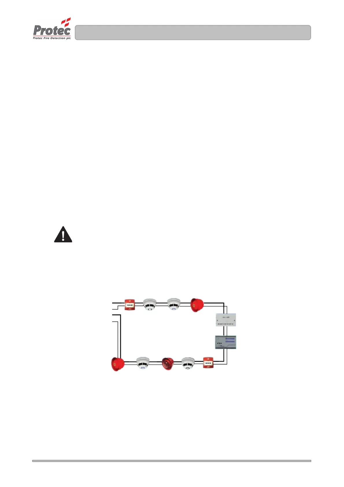
The loop wiring must be wired from the panel terminals marked ‘LA+ and LA-’ round all the loop devices
and reconnected at the panel terminal marked ‘LB+ and LB-’ ( see figure 4.0 ).
Most Protec loop devices incorporate an integrated short circuit loop isolator. No more than 20 loop
devices must be connected between isolators, and a loop isolating device must always be used on a
zone boundary ( a Manual Call Point is usually used for this purpose ).
To comply with EN54-2 a Manual Call Point must be located next to the 6100, so that
any system delays ( if programmed ) will be overridden by activation of the Manual Call
Point at access level 1.
In the case of screened cables always ensure that individual segments have earth continuity ( cable
screen and / or drain wire is classed as earth ), and that the earth wiring does not touch any other
connections, or any other earthed points.
Figure 4.0 Typical 6100 loop configuration
LA-
LB+