N93-572-88 Issue 12 NH Page 17 of 52 © Protec Fire Detection plc 2020
6.7 Connecting the Standby Batteries
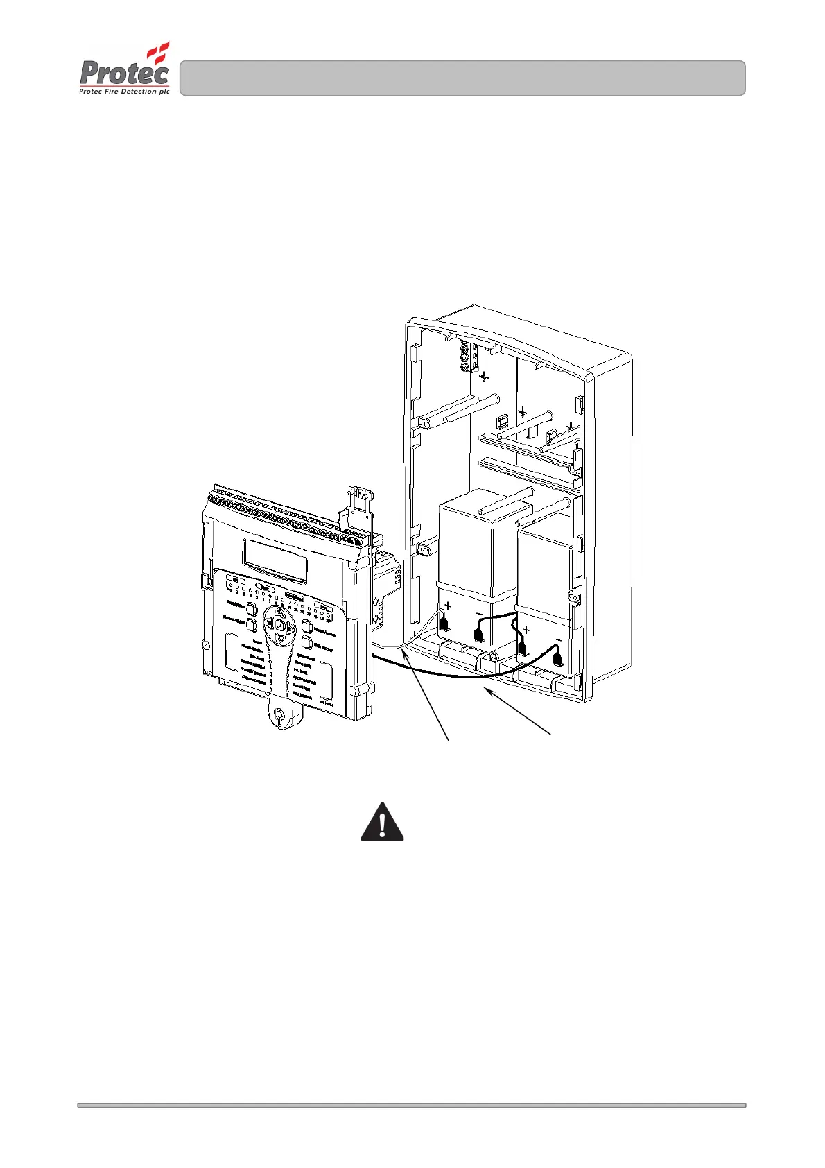
The two standby batteries must be connected in series with the battery link provided. Then,
observing correct polarity ( red lead to the positive of one battery and black lead to the negative of
the other battery ), carefully push the spade connectors of the 6100 battery leads onto the relevant
battery terminals ( illustrated in figure 6.4 ).
Please note that at this point the 6100 will not power up until the mains supply is connected.
Figure 6.4 Standby battery connections
connecting the battery leads