N93-572-88 Issue 12 NH Page 19 of 52 © Protec Fire Detection plc 2020
6.11 Connecting the Fire Link Wiring
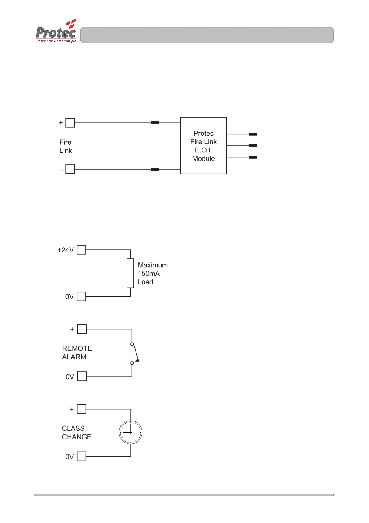
The 6100 is equipped with an output to signal to a remote monitoring station. This output is
monitored for cable faults and must only be connected to the Protec Fire Link End of Line Module
( see appendix 1 for stock code ). The End of Line Module must be fitted in the remote equipment,
and not in the 6100. If the fire link end of line module is not required, the fire link output must still be
terminated with an end of line resistor.
Figure 6.7 Fire Link Connection Details
6.12 Connecting the Auxiliary Wiring
The auxiliary wiring must now be connected if required. The auxiliary wiring comprises the class
change input, remote alarm input, auxiliary 24V supply output, global fire contacts and global fault
contacts. Note that these connections are optional and if not used do not require any termination.
Figure 6.8 Auxiliary 24V Output Details
Figure 6.9 Remote Alarm Input Wiring
Figure 6.10 Class Change Input Wiring