N93-572-88 Issue 12 NH Page 18 of 52 © Protec Fire Detection plc 2020
6.8 Refitting the Control PCB Housing
Ensure that all cable earth connections are sleeved to insulate them and then securely connect them
to the brass earth terminals in the back-box.
Carefully route the battery leads ( from the rear of the control PCB housing ) down between the two
batteries.
If the 6100 is equipped with a fire brigade panel controller, ensure the ribbon cable connected to the
back of the control PCB housing is located over the top of the control PCB housing when refitting
into the back-box.
Replace the control PCB housing ( a reversal of removal ), ensuring it is pushed flush to the back box
and that the battery leads do not get trapped. Secure with the four screws removed previously, taking
care not to over tighten the screws.
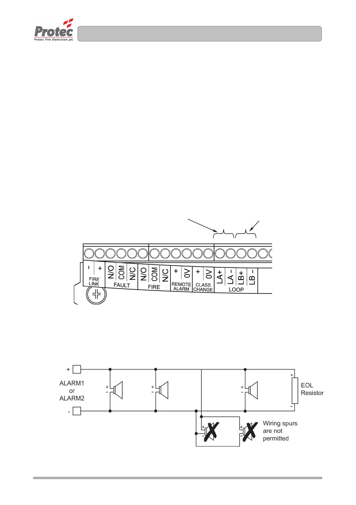
6.9 Connecting the Addressable Loop Wiring
The 6100 loop wiring must always be connected as a complete loop ( LA + and LA - connections ) to
each device, then back to the panel again ( LB + and LB - connections ). Please see figure 6.5 and
refer to figure 4.0.
Figure 6.5 Loop Connection Details
6.10 Connecting the Conventional Alarm Circuit Wiring
The 6100 can drive two conventional alarm outputs. These must be connected as shown in figure
6.6. Unused outputs must still be terminated with an end of line resistor locally in the panel.
Figure 6.6 Conventional Alarm Output Connection Details
Outgoing loop connections