N93-572-88 Issue 12 NH Page 13 of 52 © Protec Fire Detection plc 2020
6.0 Installing the 6100
The 6100 may be surface or flush mounted ( no extra bezel is required when flush mounting ).
The 6100 circuit board is fully enclosed within a sealed control PCB housing. The control PCB housing must
never be opened. If the 6100 requires repair it must be sent back to the Protec factory.
The batteries are fully accessible with the control PCB housing removed from the back-box.
The 6100 must be located internally in an area that is not subject to dampness, direct sunlight,
extremes of temperature or physical abuse. The environmental limits are given in section 10.0.
6.1 Unpacking
Carefully open the cardboard carton ( do not use a sharp object ) and remove the packing fitments,
manuals and spares pack.
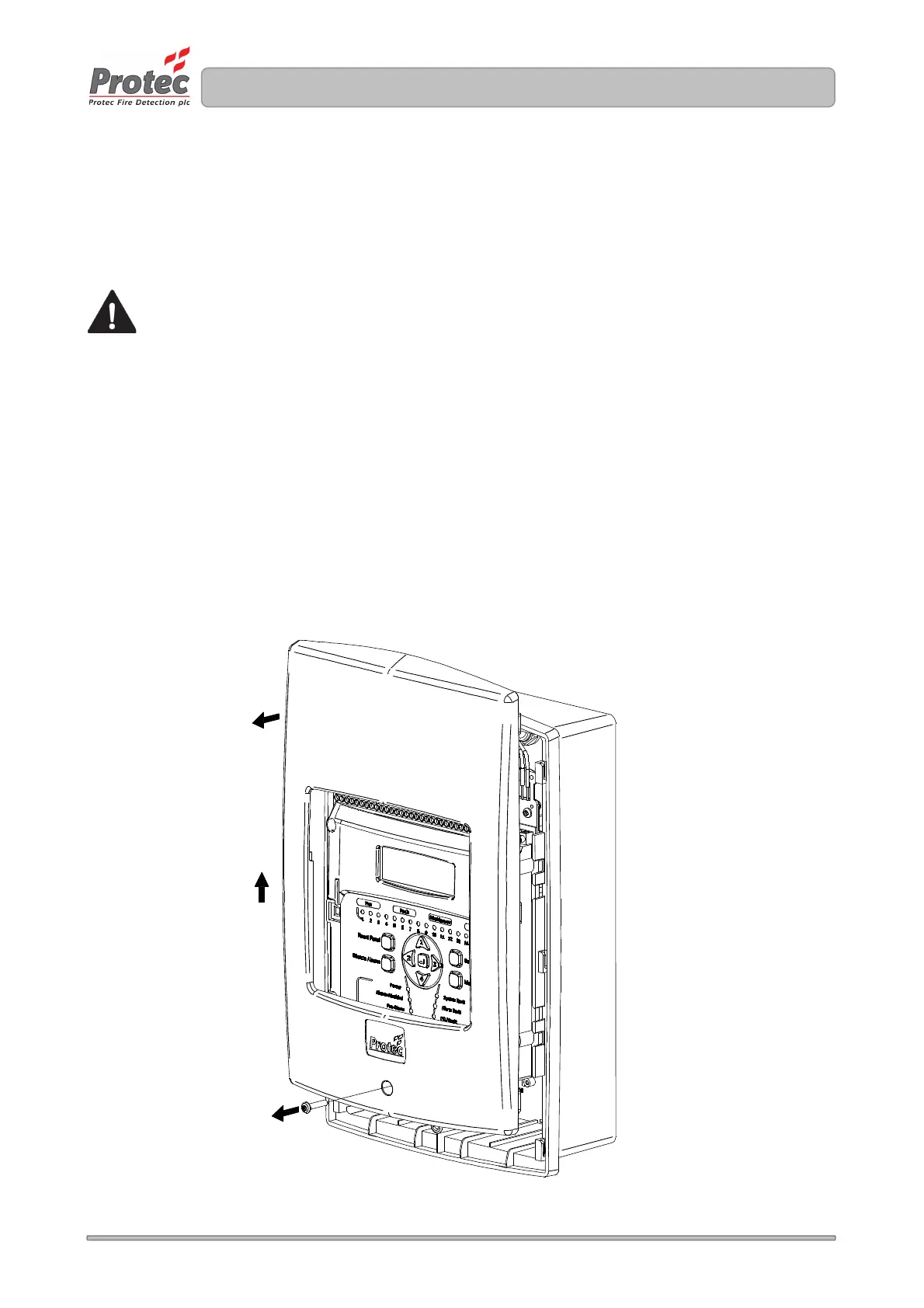
6.2 Removal of the Door
Remove the 6100 from the packaging then, using a T15 Torx® type security tool, unscrew but do not
withdraw the fixing screw from the bottom of the panel housing front as shown in figure 6.0 stage 1.
( stage 1 ).
Slide the door upward from the bottom and pull away as shown in figure 6.0 ( stages 2 and 3 ).
Put all removed parts in a safe, dry place.
Figure 6.0 Removing the 6100 door