page 29
Industrial Power Corruptor Manual Rev 1.00
3.3 Rear panel connections
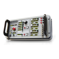
3.3.1 Instrument power
Find the AC inlet on the lower left of the rear panel. Connect
instrument power here; see specifications for acceptable voltages and
frequencies. The instrument power supply automatically adjusts to the
voltage and frequency.
There are two sources of power in your IPC: this connector, and the
power connections to the lar
ge terminal blocks on the rear panel. To
remove power, remove both sources.
(The IPC in the photo at right has the Breaker Motor Drive option
installed.)
3.3.2 Source and load connections
Your IPC has 10 large gray terminal blocks on the rear panel that
have color
-coded labels to help identify them. Use these terminal blocks
to insert your IPC between your power source and your equipment that
you want to test.
The terminal blocks are divided into 2 groups; the "from SOURCE"
terminal blocks on the left side of the circuit breaker
, and the "to LOAD"
terminal blocks on the right side of the circuit breaker. For instructions
on how to configure wiring connections to these terminal blocks, see
the section in this manual on Connecting Test Power.
A 7/32-inch T-handle hex wrench is supplied with your IPC for
tightening the terminal blocks.
The terminal blocks accommodate stranded wire ranging from
ranging in size from 35 - 90 mm
2
(#2 -4/0 AWG).
If you are using wires smaller than 35mm
2
(#2 AWG) , use the wire
adapters provided with your IPC to ensure safe clamping. If a terminal
block has no wires installed, then it is a good practice to install the wire
adapters in these locations also. A 3/16-inch T-handle hex wrench is
supplied with your IPC for tightening the wire adapters.
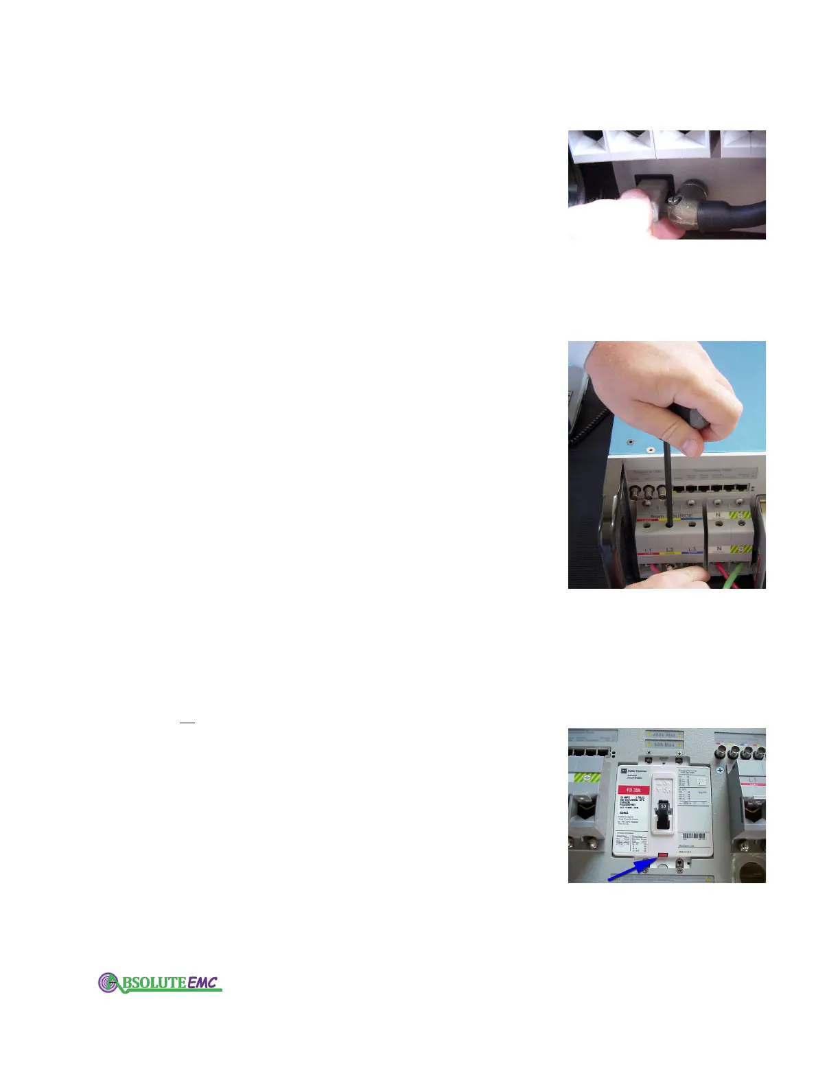
3.3.3 Main circuit breaker
The main circuit breaker disconnects the "from SOURCE" terminal
block from the "to LOAD" terminal blocks.
This circuit breaker does
not interrupt the IPC’s instrument power.
If an optional motor operator is not installed then the operating
handle and position indicator are exposed.
The circuit breakers' voltage and current rating match the internal
design of your IPC. Your IPC’s software and firmware continually
monitor the state of the circuit breaker, and trip it when the IPC is
turned off, or when an error condition is observed.
The blue arrow in the photo at right points to the manual trip test
button.
absolute-emc.com
Phone:703-774-7505
info@absolute-emc.com