page 24
Industrial Power Corruptor Manual Rev 1.00
3.2 Front panel features
The front panel of your IPC is the primary functional interface. It
has been design to be as user friendly as possible, while allowing
maximum functionality and information display.
It is separated into 3 main sections:
" The Status section where the main status display is
located, along with instrument power switch/status indication, PC
connection, and circuit breaker control/status indication.
" The Disturbance Settings section, where you will find
the switches and displays required for selecting and starting/stopping
events.
" The Meters section, where the 3 sets of meter displays,
and the high and low voltage input connectors are located.
Many of the switches have a safety cover to prevent inadvertent
operation. To operate the switch, gently raise the safety cover from the
bottom.
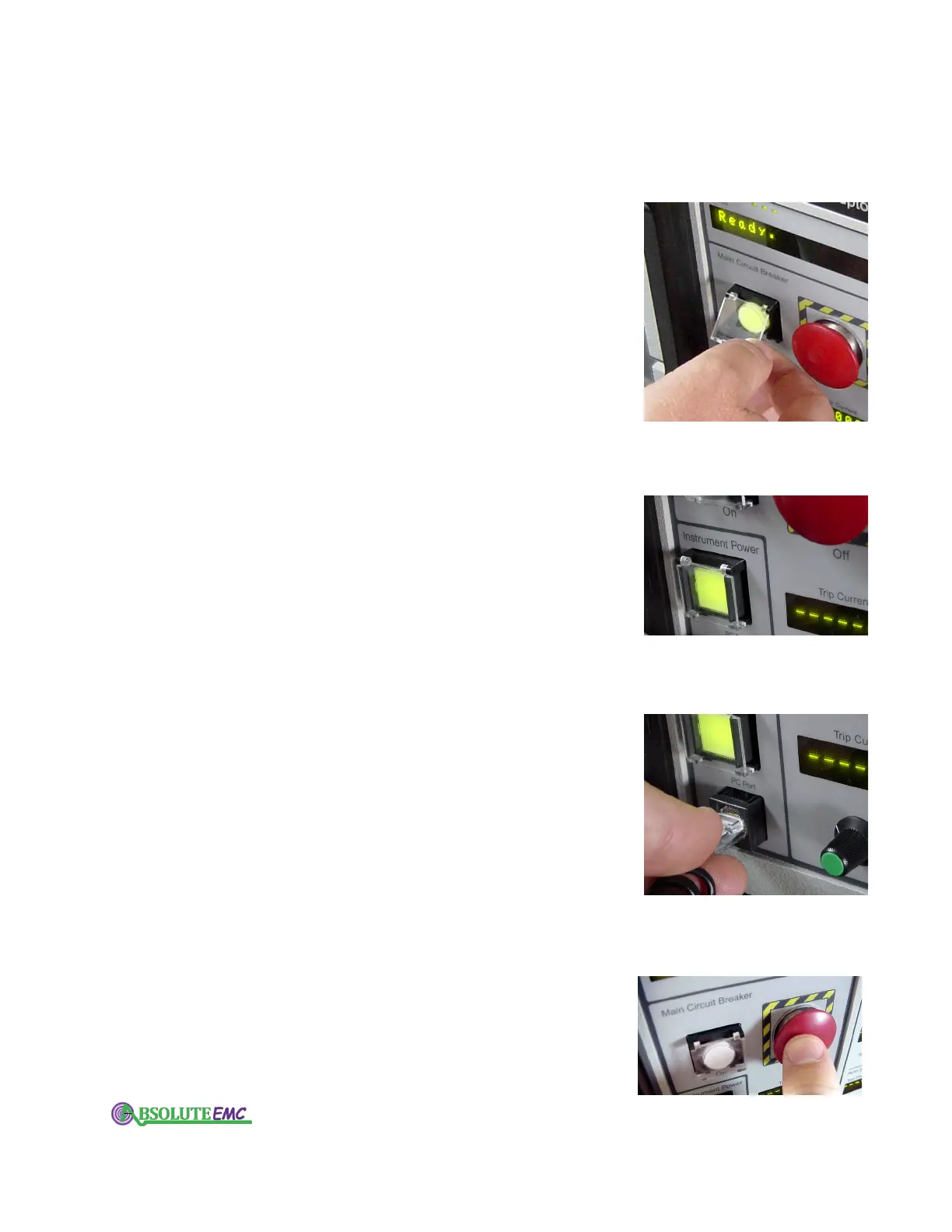
3.2.1 Instrument power switch
The push-on, push-off Instrument Power switch on the lower
left of the front panel turns your IPC on and of
f. This is also a
backlit switch that changes from green when in the on position,
to red when off. (A yellow light indicates inadequate voltage on
the IPC’s internal 24V power supply.)
Note that when you turn your IPC either on or off, the main
circuit breaker is automatically tripped open.
3.2.2 PC port
There is an RJ-45 jack on the lower left of the front panel of
your IPC.
This is used to connect to your computer. A cable and
adapter are provided with your unit to enable direct connection
to the DB-9 serial port on your computer. If your computer has a
USB port, and no 9-pin serial connection, you will require a
USB-Serial adapter. We recommend using a Belkin model
F5U103.
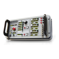
3.2.3 Circuit breaker control
The Main Circuit Breaker emergency off button is a standard
feature on all IPC’
s. This is the large round red button on the
left side of the front panel.
Pushing this button will immediately trip the circuit breaker
on the rear of your IPC. This action will also change the status
light of the Circuit Breaker "ON" switch/lamp, from green to
red. Tripping this circuit breaker will disconnect the "from
absolute-emc.com
Phone:703-774-7505
info@absolute-emc.com