page 59
Industrial Power Corruptor Manual Rev 1.00
the Panic signal, and the main circuit breaker is tripped. On the Power Supply board, the AC supply is fused on both line
and neutral, and has MOV sur
ge suppressors. From the Power Supply board, the AC supply then passes through a cable to
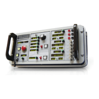
the Front Panel Board, where the IPC on/off switch is located. AC returns from this switch, on the same cable, to the IPC
power supply. The IPC has a single 24V dc power supply. 24Vdc from this supply is brought to the Power Supply Board
via a short jumper cable. Several large electrolytic capacitors on the Power Supply Board back up the 24V dc. Each
separate circuit board in the IPC has one or more switching regulators to convert the +24Vdc to +5Vdc, +/-12 Vdc, and/or
+/-15 Vdc. Some of these switching regulators provide isolation and floating signals for communication.
External communication and control:
The IPC communicates serially at 115k baud to a Windows program running on a user-supplied computer. The serial
communication ports are all floating from earth, with at least 1kV
of isolation. The Ethernet port also floats with 1kV of
isolation. Three control signals are available on rear-panel BNC connectors: Panic, Arm, and Trigger. All three are open-
collector, active-low signals, weakly pulled up internally to +24V. Panic may be asserted externally by shorting the Panic
connector. Arm and Trigger may be used externally to trigger data acquisition devices.
Data acquisition:
The IPC contains many differential-input data acquisition channels. The standard full-scale ranges are ±1000V ,
±100V
, and ±1000A. The channels are fully differential, and are equipped with 5kHz low-pass filters. A variety of A/D
schemes yield effective resolutions ranging from 12 bits plus sign to 16 bits plus sign. For Power Flow mode, the IPC
phase-locks its 128-sample-per-cycle to the L1-N channel (if N is not in use, this is effectively L1-PE). For Disturbance
Mode, no sampling is used. For breaker trip monitoring, average-sense RMS-calibrated 16-sample-per-cycle is used. All
offset calibration is performed in firmware, using factory-set constants stored in Flash. No gain calibration is required.
Sag/swell generation:
The IPC uses a patent-pending multiple-tap auto-transformer to generate sags and swells. The transformer has the
equivalent of taps at every 2.5% from 0% to 125%. Relays configure the taps, and connect the transformer to the appropriate
phases and neutral if necessary
. A pair of IGBT switches transfer the output from the 100% tap to the selected tap, then
back to 100% tap at the end of the event. Using a patent-pending technique, the IGBT's are bypassed by electromechanical
relays during the event, to minimize power dissipation, allowing the IGBT's to be used only during the transitions. The
IGBT module has a patent-pending set of snubber circuits, which include fuses. Optically-isolated sensors detect if any of
the fuses have operated. The IGBT module also monitors its internal temperature and overcurrent limits.
Protective earth:
The IPC senses current on every protective earth terminal, and asserts Panic (i.e. trips the main breaker) if excessive
current is observed. Every element of the IPC chassis and enclosure has a dedicated, solid copper buss link connecting it
to protective earth.
absolute-emc.com
Phone:703-774-7505
info@absolute-emc.com