IMP+ INSTRUCTION MANUAL
16
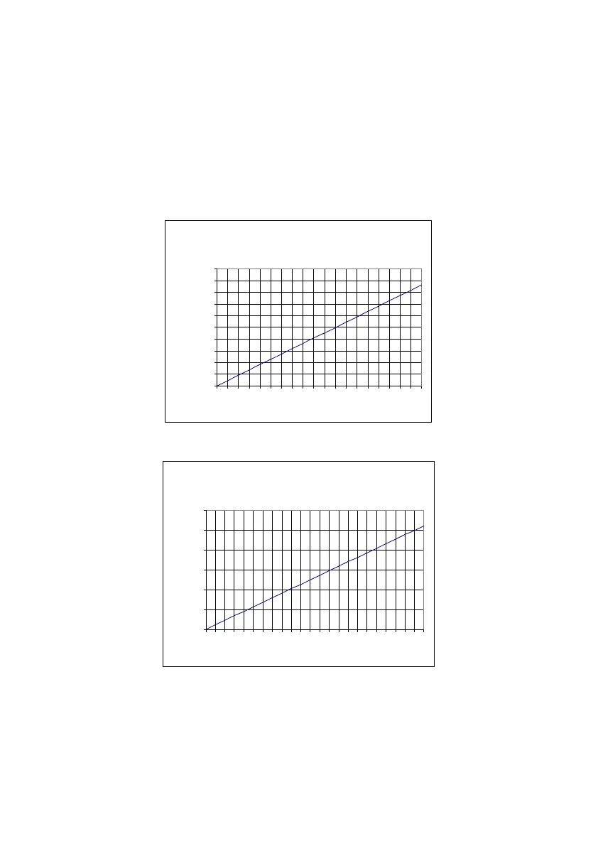
Loop Resistance
For two wire operation, the maximum cable resistance allowable can be
calculated from the graph below. For example, if an IMP+ were supplied
from 24v connected as a 2-wire unit (4-20mA only), the maximum total cable
resistance is 590 ohms, for a typical 77 ohm /km cable this would mean a
maximum cable length of 590/77 = 7.6km, remember this total cable
resistance, so this figure has to be divided by 2 to give 3.8km max distance.
Maximum cable resistance vs supply voltage for 2 wire mode.
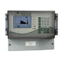
Maximum cable resistance vs supply voltage for 3 wire mode.