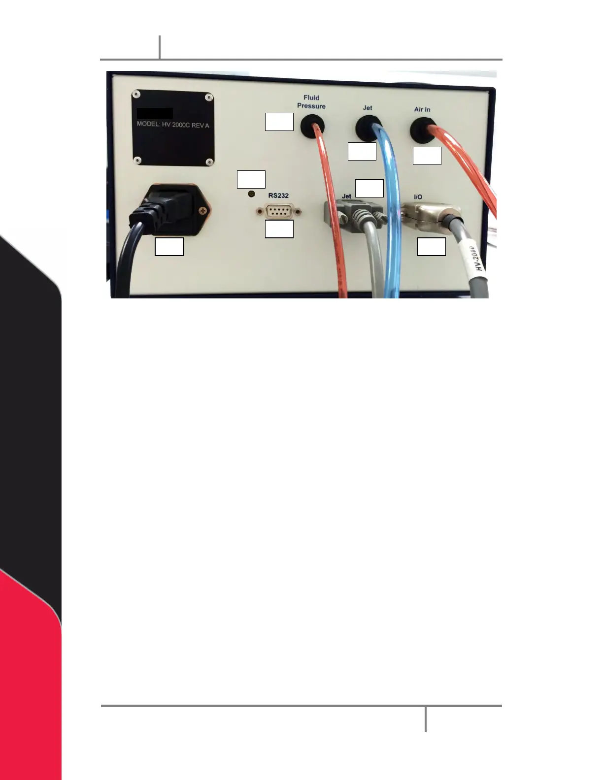
Figure 32: PVA JDX Jet Valve Controller Rear Panel
12. Air inlet – This port should be connected to the source pressure with a 6mm
diameter hose.
13. Jet Pressure outlet – This port provides air pressure for the jet dispenser and
should be connected with a 6mm diameter hose.
14. Fluid Pressure outlet – This port provides fluid delivery air pressure and should
be connect to the fluid syringe with a 4mm diameter hose.
15. LCD contrast adjustment – The adjustment changes the contrast level on the
LCD display by rotating the switch with a small screw driver.
16. AC connector with fuse– Power is supplied here and one fuse is required. The
controller can operate from 100 to 240 Vac. Operation in different countries is
easily accomplished by using a locally acceptable power cord.
17. RS-232C – Serial communication connector.
18. Jet connector – this connecter should be connected to the jet electrical
connector using the approved cable supplied with the system. This connecter
sends output trigger signals for the dispensing jet and heater settings.
19. I/O connector – This connector is used to trigger the dispensing recipes and
outputs, busy flag, and error signals from the pressure gauges and heater
controller.