45
13'
40
35
3
61
20
L IN C
ENTIMETRE
S
z 25
ME
111211
ME
====.1
1
11M
%II IIIIMIIM
.... ........
20
......
.......
..
EIIILI
ILIIMIIIIII
. ......
=Mal&
11==MHELMEMEME"
;....
IMUM
IINIM=INUEMEMENEM
MENIMIIIMMENNEN
um
....
reraramm
awn
1111
Nam
:En
::::::::
To
Ohnraral
mon
.....
.....
ANTENNA TYPE GX100 & H
=
L11-1f
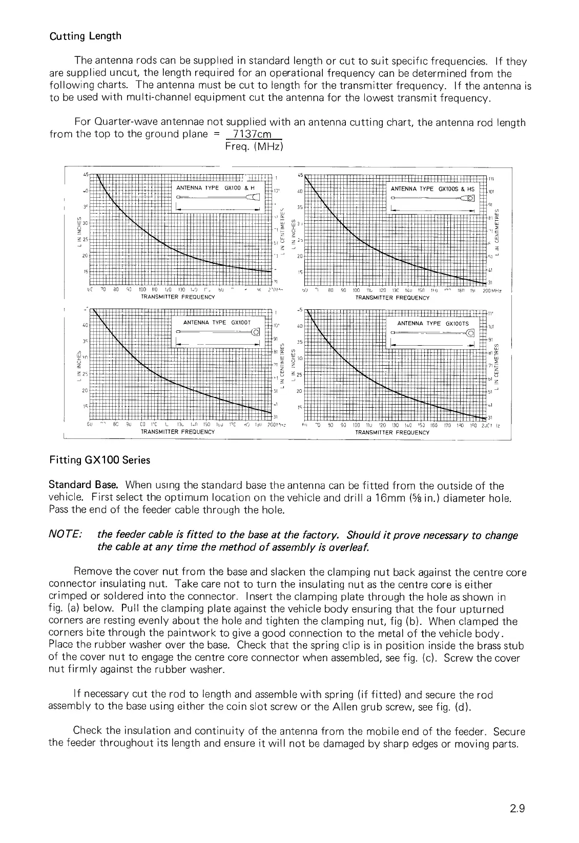
Cutting Length
The antenna rods can be supplied in standard length or cut to suit specific frequencies. If they
are supplied uncut, the length required for an operational frequency can be determined from the
following charts. The antenna must be cut to length for the transmitter frequency. If the antenna is
to be used with multi-channel equipment cut the antenna for the lowest transmit frequency.
For Quarter-wave antennae not supplied with an antenna cutting chart, the antenna rod length
from the top to the ground plane = 7137cm
Freq. (MHz)
SC
80 50 100 110 190 130 189 5
-
TRANSMITTER FREQUENCY
91
51
5
41
31
55
"
80
90
100
114
120
13C
14u
1511
1 0
''
1811
191
200 MHz
TRANSMITTER FREQUENCY
1
11111111'111f
11111111
111111
ANTENNA TYPE GX100S & HS
101
+H111111111111
'.5
1111111111111111111111111;111
40
35
5n
25
20
ANTENNA TYPE GX100T
10'
40
91
35
30
25
51
J
20
ANTENNA TYPE GX100TS
-C1
_
L
-
81
1U1
91
81
71
a
bi
z
51
—
Namill!!!!!
'MOIL
Ifl
15
Cu
SC 9u CO I'C 13 135 5, 150 Ituu
TRANSMITTER FREQUENCY
5'C
lull
31
31
2001,
511
90 90 100 Ilu '20 130 140 '53 160 170 190 1
0
0 2951 Iz
TRANSMITTER FREQUENCY
Fitting GX100 Series
Standard Base. When using the standard base the antenna can be fitted from the outside of the
vehicle. First select the optimum location on the vehicle and drill a 16mm (
5
/
8
in.) diameter hole.
Pass the end of the feeder cable through the hole.
NOTE: the feeder cable is fitted to the base at the factory. Should it prove necessary to change
the cable at any time the method of assembly is overleaf.
Remove the cover nut from the base and slacken the clamping nut back against the centre core
connector insulating nut. Take care not to turn the insulating nut as the centre core is either
crimped or soldered into the connector. Insert the clamping plate through the hole as shown in
fig. (a) below. Pull the clamping plate against the vehicle body ensuring that the four upturned
corners are resting evenly about the hole and tighten the clamping nut, fig (b). When clamped the
corners bite through the paintwork to give a good connection to the metal of the vehicle body.
Place the rubber washer over the base. Check that the spring clip is in position inside the brass stub
of the cover nut to engage the centre core connector when assembled, see fig. (c). Screw the cover
nut firmly against the rubber washer.
If necessary cut the rod to length and assemble with spring (if fitted) and secure the rod
assembly to the base using either the coin slot screw or the Allen grub screw, see fig. (d).
Check the insulation and continuity of the antenna from the mobile end of the feeder. Secure
the feeder throughout its length and ensure it will not be damaged by sharp edges or moving parts.
2.9