Switching —
In
the receive condition, the 10V supply is connected to the receiver oscillator
section (pin 2) via the unerergised relay R LS/2 (S1) in the Switching Module (12). Operating the
press-to-talk switch energises R LS/2 and contact S1 transfers the 10V supply to the transmitter
oscillator section (pin 4) to activate the transmitter oscillator.
Receiver and Transmitter Oscillator Module (18) 12-channel
Construction —
This plug-in module is made up of two identical switched oscillator cards (one
receiver, one transmitter) permanently fixed to an oscillator mother board. The 12-way single pole
switches fitted to each card are ganged by a spindle operated by the Channel Selector Knob mounted
on the front panel of the equipment. The module is horizontally mounted and secured by 2 x
M2,5 pillars and 2 locating pins.
Each switched oscillator card is provided with a transistor and the fixed value components
of one oscillator circuit. The oscillator mother board is provided with 24 sets (12 receive 12 trans-
mit) of frequency-conscious components, i.e. crystals, trimming inductors, shunt resistors and
decoupling capacitors (8 off). The board is arranged so that the receiver channel components
occupy the front half and the transmitter channel components occupy the rear half; the receiver
and transmitter oscillator cards are positioned centrally on the appropriate sector of the board to
connect the selected components into the oscillator circuit.
Component Coding — See Coding Table
Trimming —
Inductive; receiver trimmers L1 to L12, transmitter trimmers L13 to L24 (See also
Netting Procedure Section 2).
Switching —
In the receive condition, the 10V supply is connected to the receiver oscillator mother
board at pin 2 via the unenergised relay R LS/2 (S1) in the Switching Module (12). Operating the
press-to-talk switch energises R LS/2 and contact S1 transfers the 10V supply to the transmitter
oscillator mother board pin 4 to activate the transmitter oscillator. Channel change is effected by
the ganged 12-way switches on the cards.
Receiver and Transmitter Oscillator Module (18) 6-Channel
Apart from the number of channels provided and the component coding of the oscillator
mother board, this is identical in all respects with the 12-channel version.
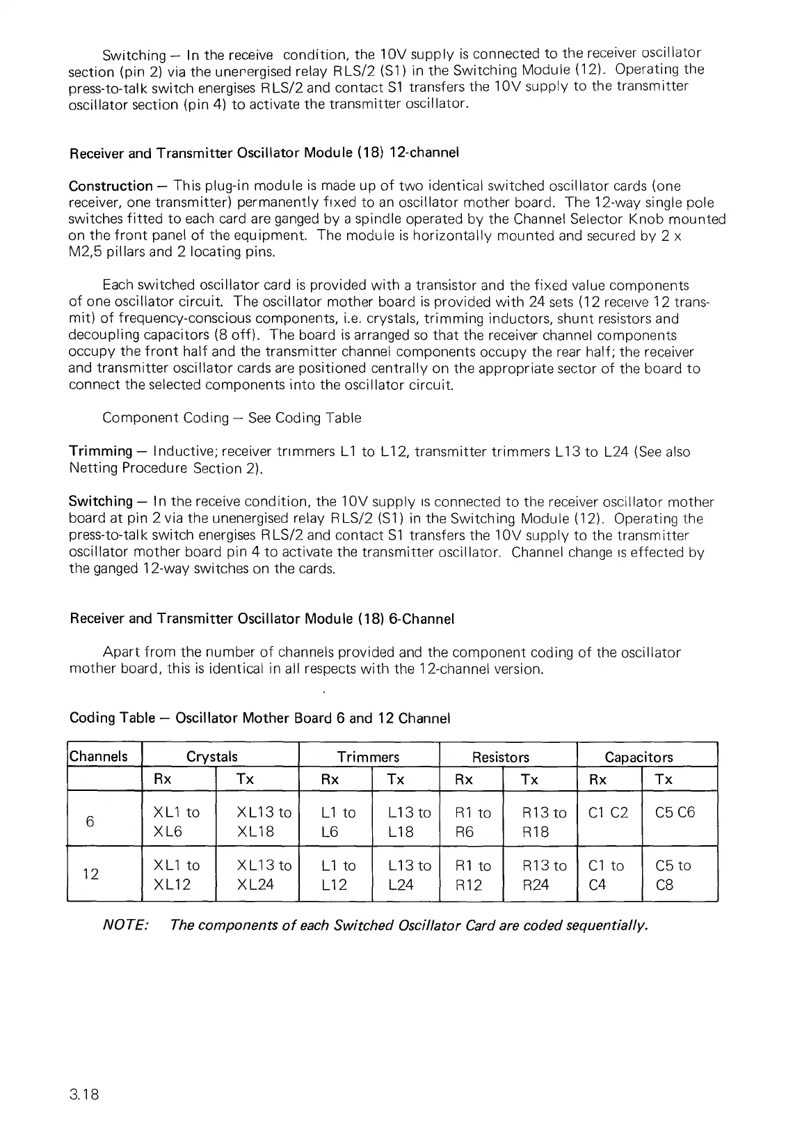
Coding Table — Oscillator Mother Board 6 and 12 Channel
Channels
Crystals
Trimmers
Resistors
Capacitors
Rx
Tx
Rx
Tx
Rx
Tx
Rx
Tx
6
XL1 to
X L6
XL13 to
XL18
L1 to
L6
L13 to
L18
R1 to
R6
R13 to
R18
C1 C2
C5 C6
12
XL1 to
XL12
XL13 to
X L24
L1 to
L12
L13 to
L24
R1 to
R12
R13 to
R24
C1 to
C4
C5 to
C8
NOTE: The components of each Switched Oscillator Card are coded sequentially.
3.18