Replacement of Plug-in Modules
When replacing plug-in modules, ensure that they are correctly orientated so that the module
sockets engage with the Mother Board pins. Reversing the module will not cause damage as pins and
sockets will not engage.
Use of M201 AM Test (Extension) Assemblies Kit (AT12867)
The complete kit consists of ten printed wire assemblies mounted in a plastic mould and
contained in a carrying case. Each assembly is designed so that the required mother board
connections are extended to a corresponding set of pins on the top edge. These, in turn, mate with
the sockets of the appropriate module. When the combination of extension assembly and module is
plugged into the motherboard, complete access to the module is available.
Test Assemblies are provided for the following modules:—
I F Amp. Detector and AGC
Squelch IF and Delayed AGC
Noise Limiter and Filter
Noise Squelch
Receiver AF Amplifier
Transmitter Low Power Audio
Receiver Osc. Multiplier
Transmitter Multiplier
RF Amplifier
Antenna Filter (Shorting Link)
It
should be noted that Test Assemblies are not required for the remaining modules as they can
be analysed in situ (10V Regulator, TX/RX Oscillator, High Power Modulator and PA Modules) or
when removed from the equipment (Control and Switching Modules).
Fault Finding — Integrated Circuits (IC's)
In the event of an apparent failure of an IC, all external components should be checked to
prove the serviceability or otherwise of the
IC
before replacing it.
It is essential that these checks are carried out as otherwise the original cause of the failure
could be still present and destroy the replacement item.
Antenna Loading
The equipment will operate safely under a wide range of loading conditions. However, the
transmitter should not be operated in the absence of a suitable load, such as a 502 wattmeter,
otherwise the transmitter output stage may be damaged.
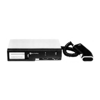
CONSTRUCTION
The equipment is contained in a robust, diecast casing consisting of frame, cover and Cover
Assembly embodying the Cradle Carrier. These two items are machined at one end to inter-lock
with rear edges (top and bottom) of the frame and each is retained by 2 screws at the front. As
they are interchangeable, the equipment can be either suspended from or mounted on the cradle.
At the rear of the frame are the microphone, antenna and facility sockets together with power lead
and loudspeaker lead outlets. The covered outlet is for the interconnection of an external option
(Amplifier A200 or Regulator VR200). The plug-in Control Module is secured to the front of the
frame by 4 Pozidriv screws. It is protected by the polycarbonate Front Panel Assembly through
which a small arc of the 3 operating controls protrude. This assembly has formed tabs on the left
hand side to lock into corresponding recesses on the frame thus forming a hinge. When closed, the
Front Panel Assembly overlaps the screws retaining the Cover and Cover Assembly; it is held in the
closed position by a spring loaded pin on the right of the frame.
4.2