r
K5
407
1
2,0V DC
10,7 MHz
FILTER
INJECT 10,7MHz
AT 1KHz UNMOD
AT 304V PD
(2 x 15K IN
PARALLEL)
L-----j
MATCHING NETWORK
(LOCALLY MADE)
FAULT LOCATION CHECKS — RECEIVER
Test Equipment Required (See Test Equipment for suitable types)
Signal Generator.
Electronic Voltmeter (EVM)
20 0005/ per volt Multimeter.
Initial Checks
Remove top and bottom covers. Refer to Fault Location Diagram
Check input voltage 13,8V, and Regulator output 9,8 — 10,3V at points shown.
Interstage Checks (Refer to Fault Location Diagram)
1.
Oscillator 0,6V RMS (EVM)
2.
Oscillator Multiplier 1,0V RMS (EVM)
3.
Inject signal at channel operating frequency 30% modulation at 1 kHz and make the following
checks at levels A,B and C (shown on diagram) using multi meter (set to 10V) except where stated
3.1 IF output
3.2 Noise Filter output (EVM)
See Fault Location Diagram
3.3 AGC
for readings
3.4 Squelch output. (levels A and B).
Should a fault be suspected between antenna and IF output, check IF module.
4.
IF Module Check
Remove 10,7 MHz Crystal Filter (2 x M3 nuts on underside of Mother Board).
Inject 25 0/ PD at 10,7 MHz, 30% modulation at 1 kHz
4.1
Check I F TP1
1V DC
4.2
Check IF output
2,0\/ DC
4.3
Check Noise Limiter output
100mV RMS
4.4
Check AGC
4,7V DC
Replace 10,7 MHz Crystal Filter
If IF module satisfactory check 10,7 MHz Filter.
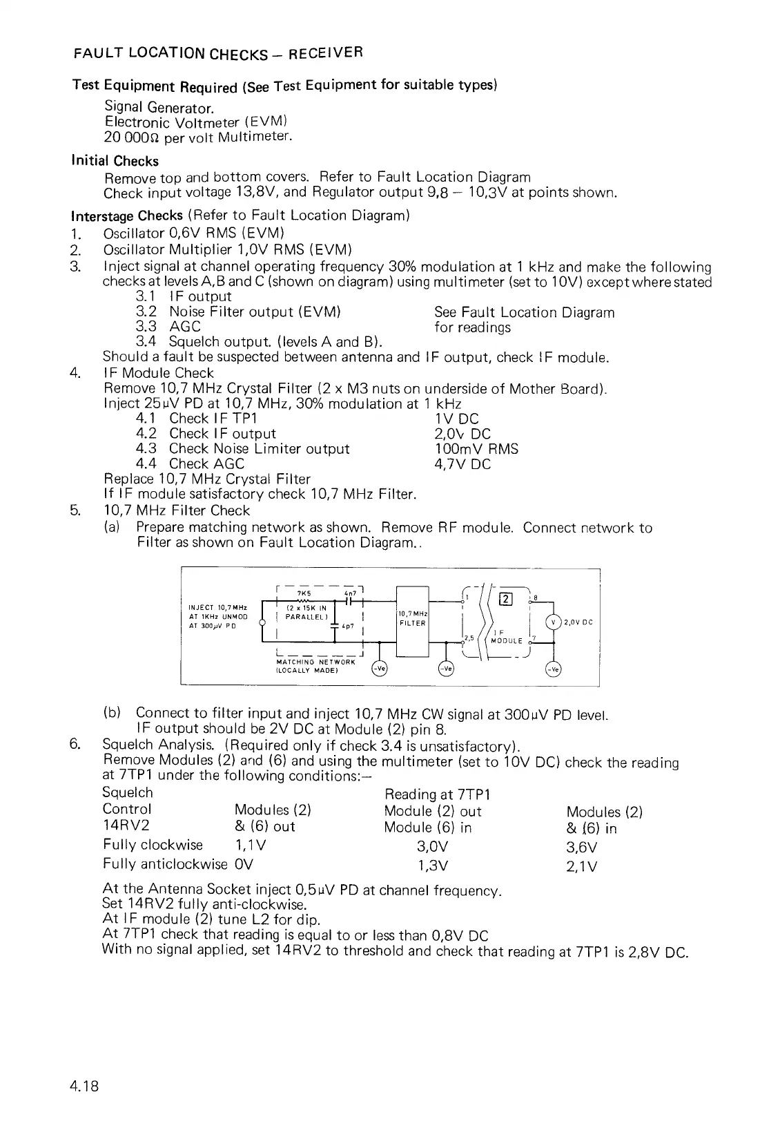
5.
10,7 MHz Filter Check
(a)
Prepare matching network as shown. Remove RF module. Connect network to
Filter as shown on Fault Location Diagram..
(b)
Connect to filter input and inject 10,7 MHz CW signal at 300 uV PD level.
IF output should be 2V DC at Module (2) pin 8.
6.
Squelch Analysis. (Required only if check 3.4 is unsatisfactory).
Remove Modules (2) and (6) and using the multimeter (set to 10V DC) check the reading
at 7TP1 under the following conditions:—
Squelch
Reading at 7TP1
Control
Modules (2)
Module (2) out
Modules (2)
14RV2
& (6) out
Module (6) in
& (6) in
Fully clockwise
1,1V
3,0V
3,6V
Fully anticlockwise OV
1,3V
2,1V
At the Antenna Socket inject 0,511V PD at channel frequency.
Set 14RV2 fully anti-clockwise.
At IF module (2) tune L2 for dip.
At 7TP1 check that reading is equal to or less than 0,8V DC
With no signal applied, set 14RV2 to threshold and check that reading at 7TP1 is 2,8V DC.
4.18