TPI
C23
4n7
C20 -LC21
T
1
° T"'
C2-.4
4n7
A OV
B
LOV
C 325V
I.F. AMP. DETECTOR & A.G. C.
2,5
4(
-
J,
? I
5
MCI
-VE
IC16
2
TR1
BF152
R3
10 TR2
PBC108
715813A
R2
C3—
202
4n7
01
RI.
BAXI6
IK
-) ii.
C10
AT27754
T
' 7
220
Rl
13
T
1-
1
-
1
'------1—.—'
-VE
C6
RI3
T
4n7
47
c, r
I
II- , ,
XTAL
100n
C9
2102
1
-•
-VE
4/1
4n7
85 C1I
1K2 Ot17
RVI It(
I.F. CA/8
I
C15-LC15 —C17
VE
-
VE
220
022
1
<no
C24
-
L
A.C28
4n7
33
Tl
R1I
7
RI2~
II
ye.
4
IC25 L26
68K
3K3
T
6
PT'
L3 n
IK2
RIO
C32
T T
' "
C29
VE
T"
7
RI2
,=,C31
1DK
T
330
'
PSA,13
TR2
100
7,9
TP1
801 I
Ig 0
021 023
1~
I
O
C7
CI
.
"
'
C 7
:Rt
_F
.
10 ,
3
1:6
T
1
113
11
CI
-.I
.--
9
6
8P
000
530[100
0
-
-
2 I ID
1 2
-
3
C2
5
6
C26
COMPONENT SIDE
UNDERSIDE
UNDERSIDE
MP 3
A 0.25V
B
2.IV D.C. RN RANGE
C 2.3V
C12
,T"
7
,
-LC13 _L CIL
r° T"'
AT2TI54
E
9
C
2
3
01
4
c3
5
'4
COMPONENT SIDE
1 13 II 12 8 10 9
IC2
14
2
3
6
7
14
13
11
12
10
IC3
2
3
5
i
fy,
a IT
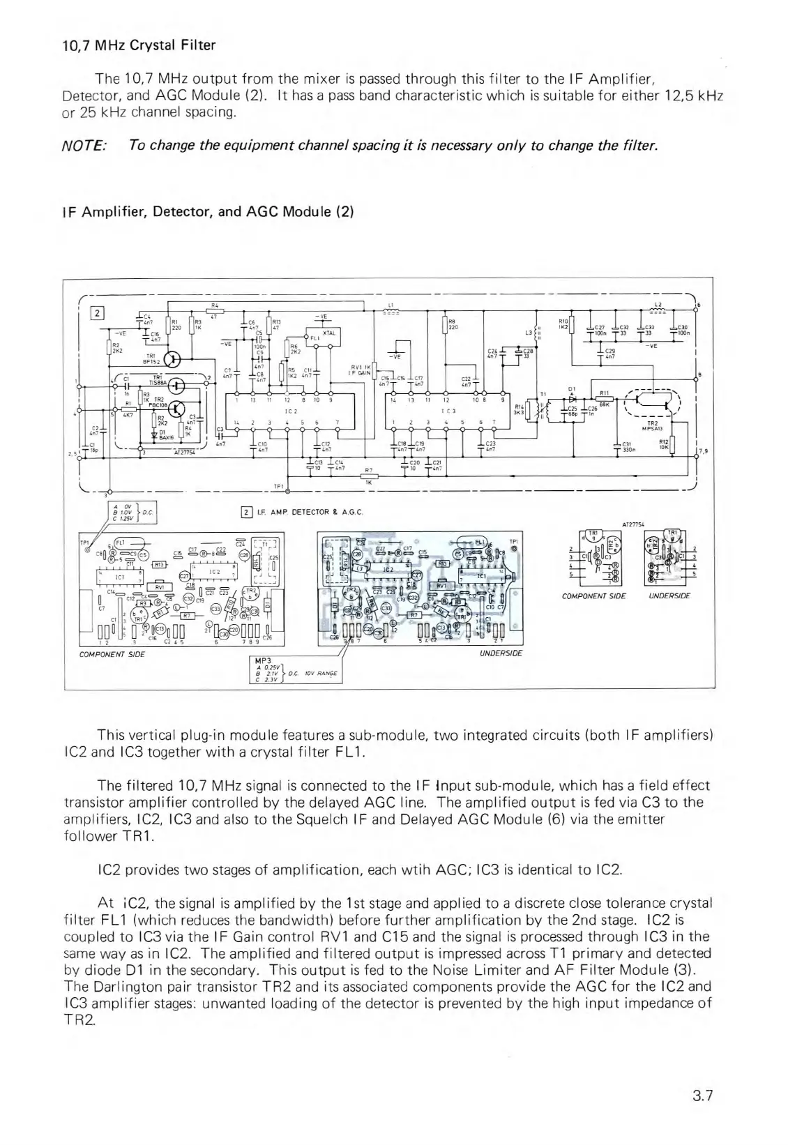
10,7 MHz Crystal Filter
The 10,7 MHz output from the mixer is passed through this filter to the
IF
Amplifier,
Detector, and AGC Module (2). It has a pass band characteristic which is suitable for either 12,5 kHz
or 25 kHz channel spacing.
NOTE: To change the equipment channel spacing it is necessary only to change the filter.
IF Amplifier, Detector, and AGC Module (2)
This vertical plug-in module features a sub-module, two integrated circuits (both IF amplifiers)
IC2 and IC3 together with a crystal filter FL1.
The filtered 10,7 MHz signal is connected to the
IF input
sub-module, which has a field effect
transistor amplifier controlled by the delayed AGC line. The amplified output is fed via C3 to the
amplifiers, IC2, IC3 and also to the Squelch
I
F and Delayed AGC Module (6) via the emitter
follower
TR1.
IC2 provides two stages of amplification, each wtih AGC; IC3 is identical to IC2.
At iC2, the signal is amplified by the
1st
stage and applied to a discrete close tolerance crystal
filter FL1 (which reduces the bandwidth) before further amplification by the 2nd stage. IC2 is
coupled to IC3 via the
IF
Gain control RV1 and C15 and the signal is processed through IC3 in the
same way as in IC2. The amplified and filtered output is impressed across T1 primary and detected
by diode D1 in the secondary. This output is fed to the Noise Limiter and AF Filter Module (3).
The Darlington pair transistor TR2 and its associated components provide the AGC for the IC2 and
IC3 amplifier stages: unwanted loading of the detector is prevented by the high input impedance of
TR2.
3.7