UNDERSIDE
M P11
0.75V P
ro
P
R9
R2
9.5
IC10
100
150
I
I
•
E1
10
3
9.2
10
ICI
R8
C16
22
47K
1
22
C9
8.9
In
—VE
3
4.6
10
—VE
2.5
433
3
6
0
5
20
4.0
DI
LQ
02 *
/C6
1
47K
R3
RV3
5K
270
1K5
I
R6
R7
RV1
5K
GAIN
R5
1
—
•
R11
R4
I
R V2
RIO
68K
18K
I
47K
390
1C4
C8
C2 /C3 —C12
C5
22
—
"22
C15 /C7
470P
5
2
.
7 4.8
4.6
T
2 2
/
-22
T
in
7
—0
4
O
3
U
LOW POWER TX AUDIO
T''
J
7
5
2
1.6
9.1
6.0
C11
RI
in
C14
330
4n7
TF3
LOW PASS
FILTER &
GAIN
TF2
GAIN &
) HIGH PASS
FILTER
TF1
MIC /AMP (
COMPRESSOR
COMPONENT SIDE
If the level of the receiver signal lies between zero and 0,250V PD (approx.) then the
demodulated output of Module (6) will consist substantially of noise and audio.
The input stage is a high pass active filter, C1,R3,C2,R2,R4,R5,TR1,TR2 which removes the
audio content. The noise is fed to the amplifier TR3, TR4 and detected by the diodes D1,D2 (in
a voltage doubler configuration) and the resultant DC is applied to TR5 base to operate the Schmitt
Trigger, (TR5, TR6) the level of this potential being controlled by RV2 (Squelch) at the Control (14).
The high potential at TR6 opens the squelch gating diode D3 which in turn is applied to the
base of the squelch switch transistor in Module (4). A second path from TR6 collector is via the
Darlington transistor TR7 and also TR8, which provides the means of driving a 'Busy' indicator at a
facility module.
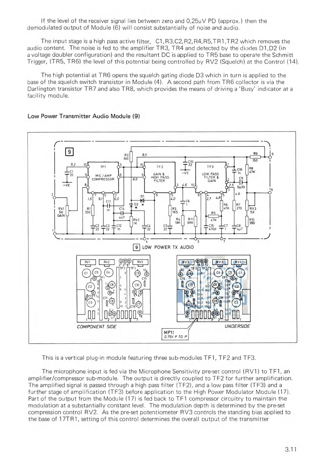
Low Power Transmitter Audio Module (9)
This is a vertical plug-in module featuring three sub-modules TF1, TF2 and TF3.
The microphone input is fed via the Microphone Sensitivity pre-set control (R V1) to TF1, an
amplifier/compressor sub-module. The output is directly coupled to TF2 for further amplification.
The amplified signal is passed through a high pass filter (TF2), and a low pass filter (TF3) and a
further stage of amplification (TF3) before application to the High Power Modulator Module (17).
Part of the output from the Module (17) is fed back to TF1 compressor circuitry to maintain the
modulation at a substantially constant level. The modulation depth is determined by the pre-set
compression control RV2. As the pre-set potentiometer RV3 controls the standing bias applied to
the base of 17TR1, setting of this control determines the overall output of the transmitter
3.11