1
MOD
DRIVER
r
,9,
LOW POWER
TX AUDIO
MIC AMP
&
LP FILTER
til
COMPRESS
HP
GAIN
FILTER
& GAIN
DISTORTION CORRECTION
COMPRESSION FEEDBACK
MOD
DRIVER
BUFFER
AMP
ri
Ld
P A MODULE
I
POWER
AMP
1
J J
RX RF MODULE
1
17 HIGH POWER
TX
1
MODULATOR
F
R TX MULTIPLIER
MULTIPLIER....- AMP
H TX
OSCILLATOR
OSCILLATOR
r
13
ANTENNA
FILTER
p
12 SWITCHIN
S2
Muting
The proportion of 10,7 MHz signal passed to the Squelch IF and Delayed AGC Module (6) is
amplified and detected to provide an output of noise and audio to the Noise Squelch Module (7)
where an active filter (TR1, TR2) blocks the audio content. After amplification by TR3 and TR4,
and rectification of the residual noise the resultant DC signal is fed to the Schmitt trigger (TR5,
TR6).
If the RF signal at the antenna is very weak or non-existent, the DC signal level will be high,
and the Schmitt trigger will disable the AF module via 7D3. Under all other circumstances, the
DC signal level will be too low for 7TR5 (part of Schmitt trigger) to conduct and the receiver will
operate normally. TR7 and TR8 provide a high impedance output for an external facility module.
Delayed AGC
At higher signal levels, delayed AGC is developed and amplified in the Squelch IF and Delayed
AGC Module (6). This is applied to the 1st and 2nd RF Amplifiers and also to the input stage of the
IF Amplifier Module (2).
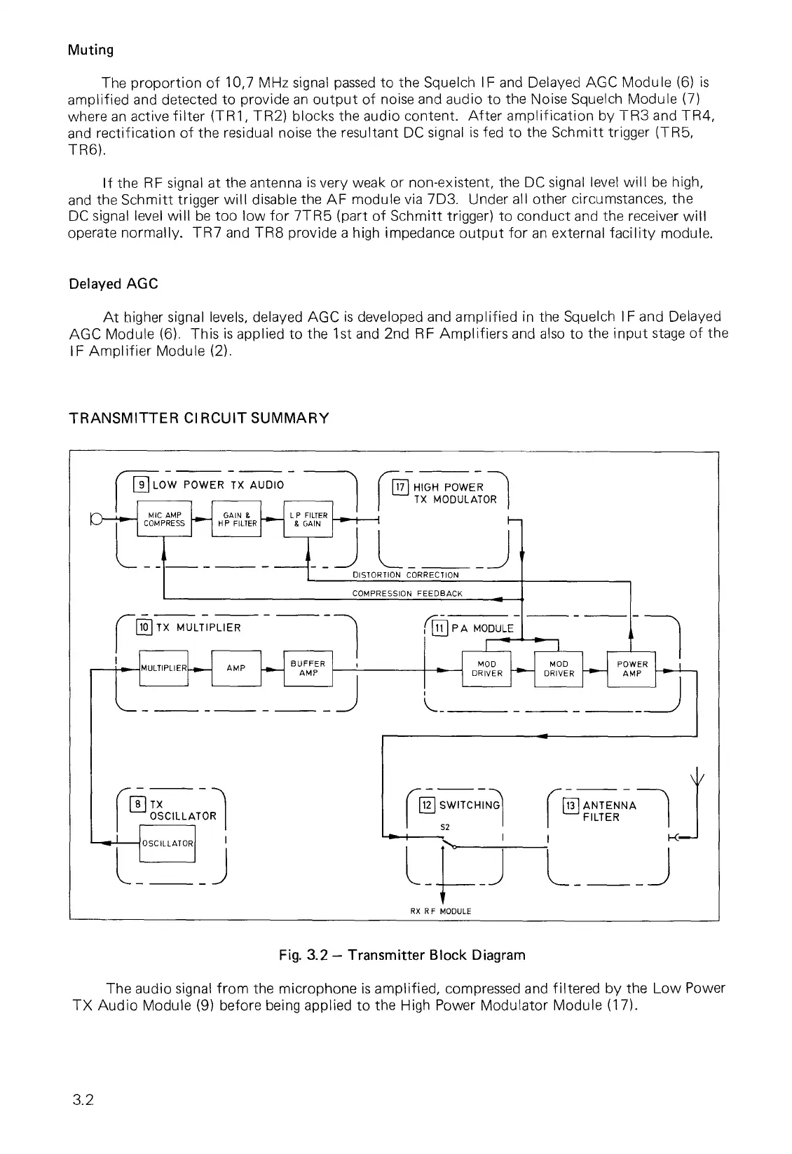
TRANSMITTER CIRCUIT SUMMARY
Fig. 3.2 — Transmitter Block Diagram
The audio signal from the microphone is amplified, compressed and filtered by the Low Power
TX Audio Module (9) before being applied to the High Power Modulator Module (17).
3.2